Hair styling appliance

a hair styling and hair technology, applied in the field of hair styling appliances, can solve the problem that hair strands can get trapped between the segments, and achieve the effect of improving the appearance and appearance of the hair

Active Publication Date: 2019-06-25
DYSON TECH LTD
View PDF44 Cites 2 Cited by
  • Summary
  • Abstract
  • Description
  • Claims
  • Application Information

AI Technical Summary

Benefits of technology

[0007]A first aspect of the present invention therefore provides a heating plate for a hair styling appliance, the heating plate having a length a depth and a width, the heating plate comprising a first continuous hair facing surface and a second surface opposite the first surface, the heating plate comprising at least one groove which run across the width of the heating plate, each groove extends from the second surface towards the first surface and allows the heating plate to flex.
[0014]Walls are preferably present on each side of each groove and the walls define the grooves. The walls are preferably from 0.01, or 0.2, or 0.4, or 0.6, or 1 to 1.2, or 1.4, or 1.6, or 2 mm wide. Preferably the walls are 0.6 mm wide. In a particularly preferred embodiment the walls are wider than the grooves as this helps to increase the thermal mass of the heating plate.
[0018]The heating plate may also further comprise a second channel which runs along the length of a side of the heating plate. Ideally a second channel will be arranged on both sides of the heating plate. The second channel(s) preferably house a resilient member. The resilient member may be a strip of resilient material which runs the length of the second channel(s). Alternatively the resilient member may be one or more springs located within the second channel(s). The resilient member is also preferably less conductive than the heating plate. The resilient member advantageously may help to allow the heating plate to flex when pressure is applied to the first surface of the heating plate. The resilient member may help to allow local flexing of an area of the heating plate.
[0021]Such hair straighteners are advantageous over prior hair straighteners because whilst the heating plate is flexible and therefore hair being straightened is subjected to controlled pressure, the first continuous hair facing surface is formed in one piece and therefore hairs cannot become trapped. This may advantageously reduce hair breakage and may improve the final style of the straightened hair.

Problems solved by technology

A problem does exist with such schemes however in that strands of hair can get trapped between the segments during use of the hair straightener.

Method used


Image

  • Hair styling appliance
  • Hair styling appliance
  • Hair styling appliance

Examples


Embodiment Construction

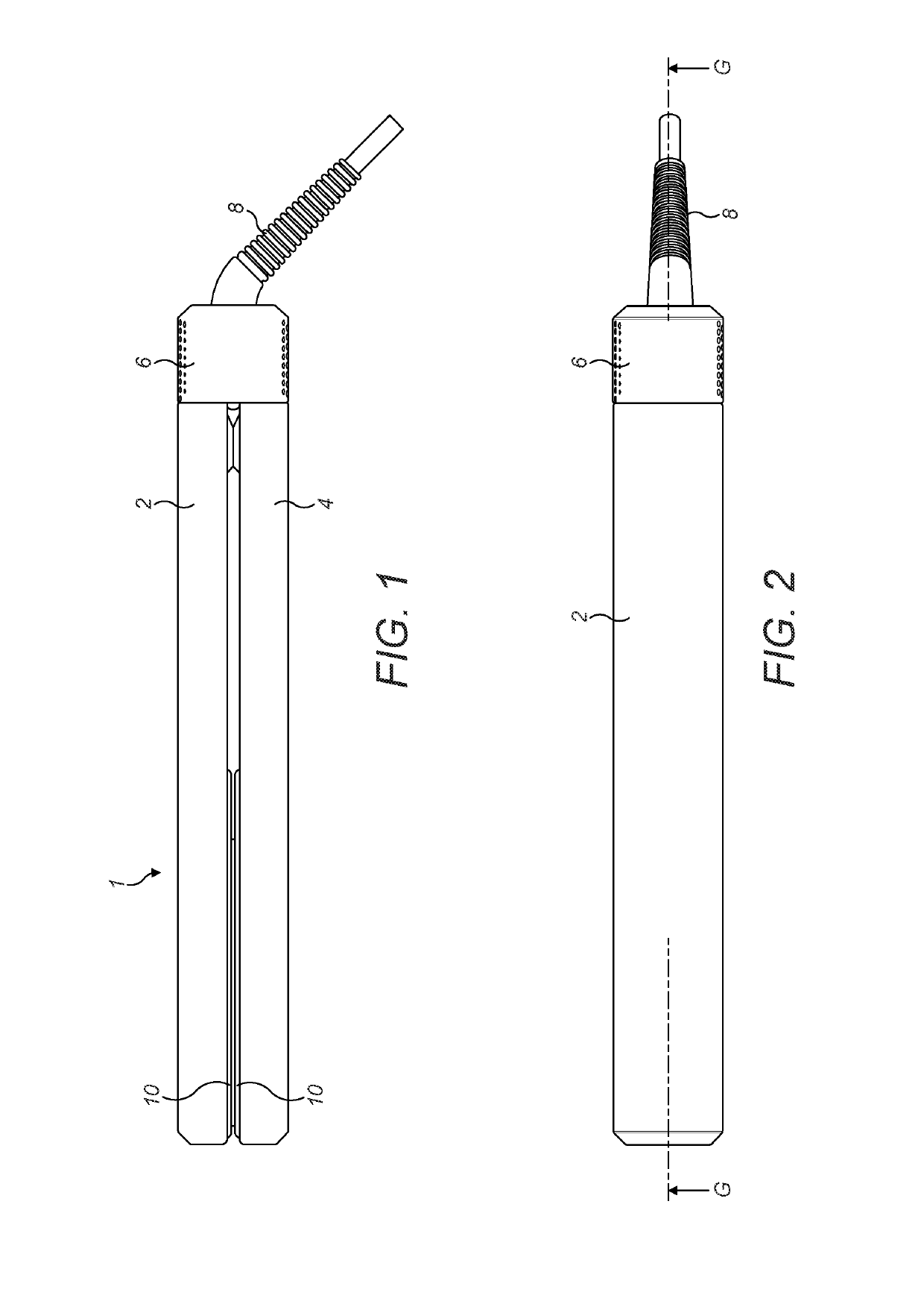
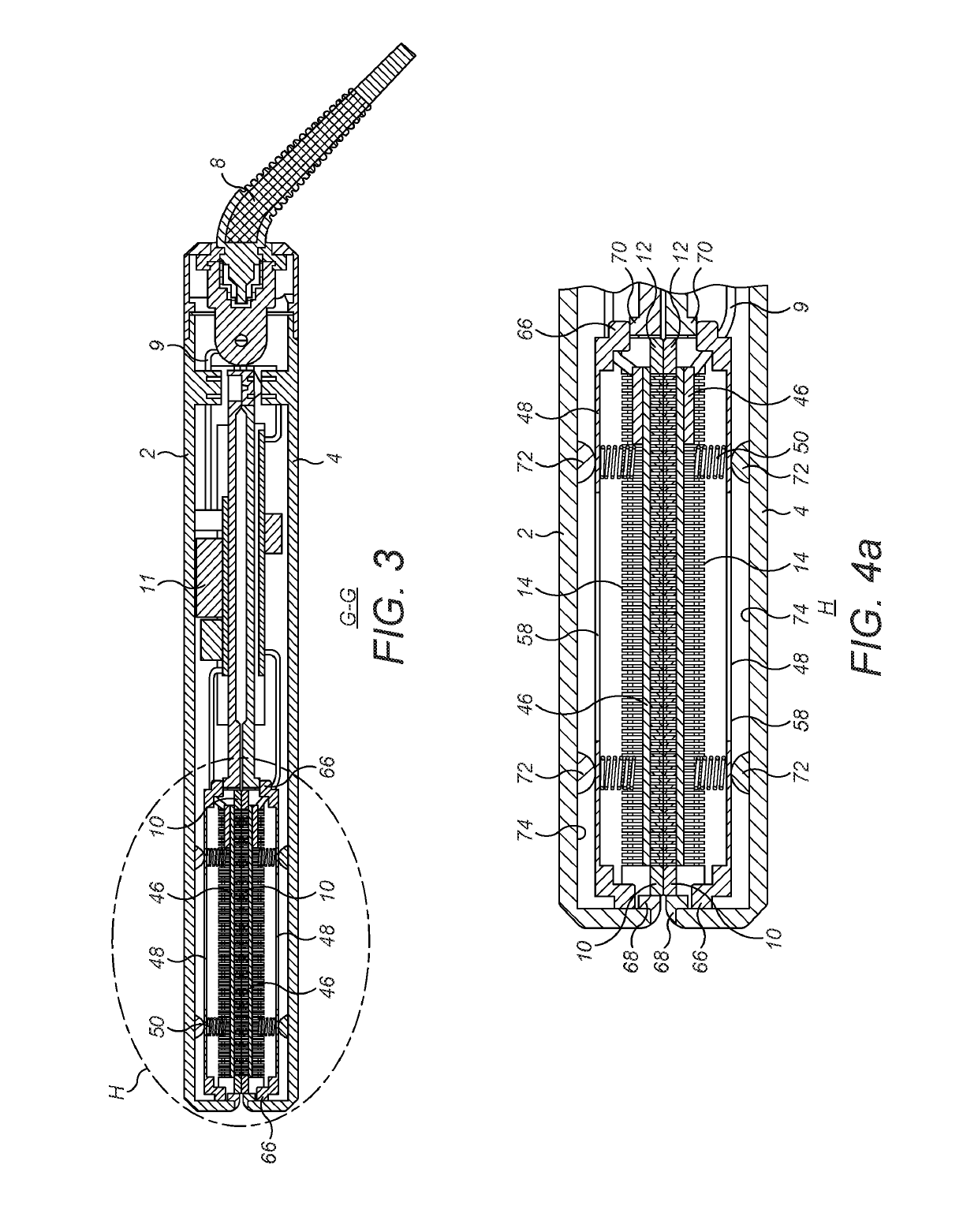
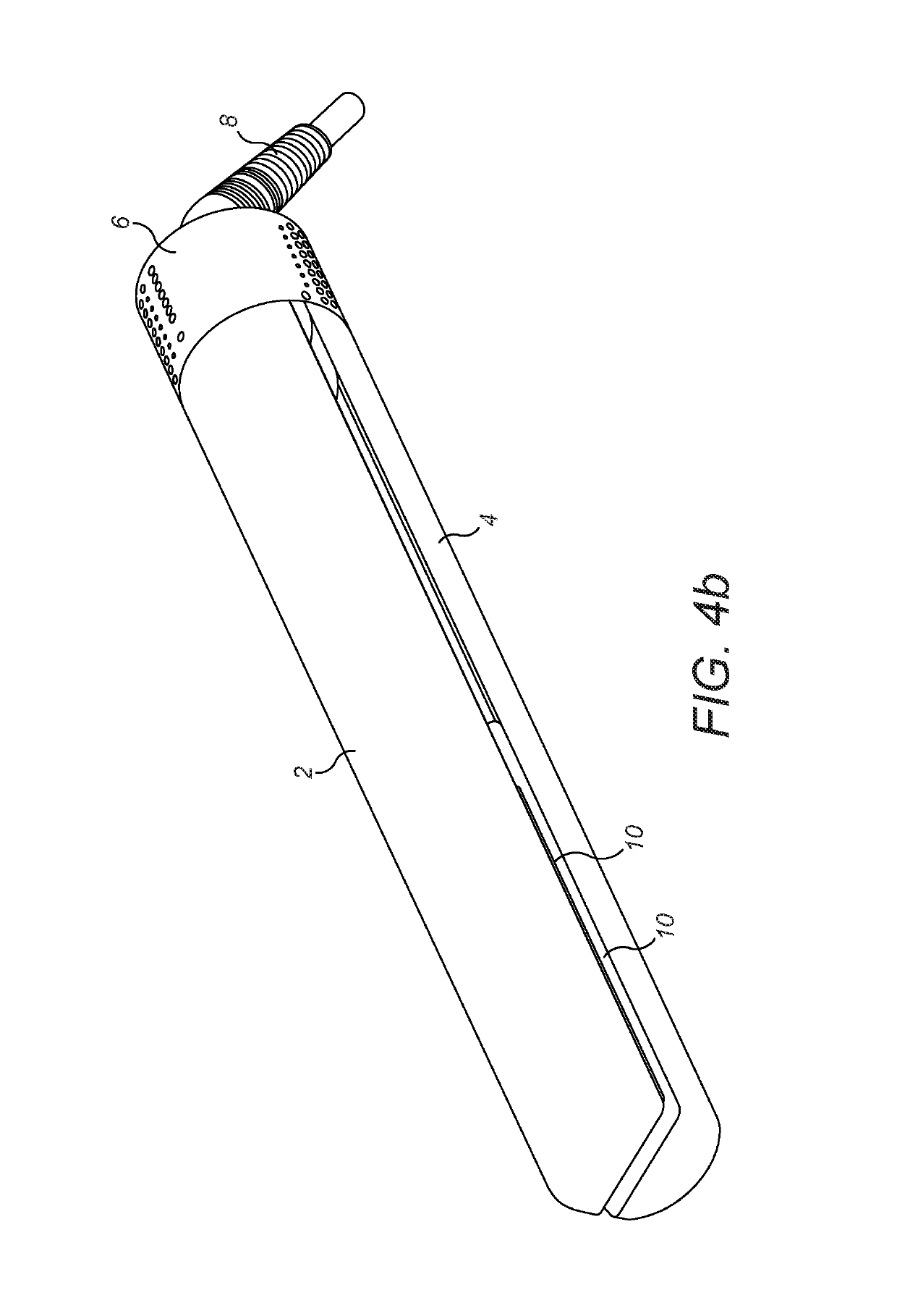
[0044]The hair straightener 1 shown in FIGS. 1 to 4c can be seen to comprise a first arm 2 and a second arm 4 which are joined together at one end by a hinge 6. A power supply cable 8 is located at the hinge end of the hair straightener.

[0045]Each arm 2, 4 further comprises a heating plate 10 located at the end of the arm furthest from the hinge 6. Wiring 9 from the power supply cable 8 connects to a printed circuit board (PCB) 11 which controls the hair straighteners 1. Each heating plate 10 has a hair contacting surface 12 and an opposed outer surface 14. The hair contacting surfaces 12 on each plate 10 are arranged such that they face each other. The arms 2, 4 are hinged such that they can move between an open position, as shown in FIG. 4c, where the hair contacting surfaces 12 are spaced apart and a closed position, as shown in FIG. 4b, where the hair contacting surfaces 12 are brought together such that hair to be straightened can be held between the hair contacting surfaces 12...


PUM


Abstract

A heating plate for a hair styling appliance, the heating plate having a length, a depth and a width. The heating plate includes a first continuous hair facing surface and a second surface opposite the first surface. The heating plate includes at least one groove which run across the width of the heating plate, each groove extends from the second surface towards the first surface and allows the heating plate to flex.

Description

REFERENCE TO RELATED APPLICATIONS[0001]This application claims the priority of United Kingdom Application No. 1521716.9, filed Dec. 9, 2015, the entire contents of which are incorporated herein by reference.FIELD OF THE INVENTION[0002]The present invention relates to a hair styling appliance. Heated hair styling appliances are designed to use the action of heat and, optionally mechanical means to form hair into a desired shape or style.BACKGROUND OF THE INVENTION[0003]In particular the present invention relates to a heating plate for a hair straightener, otherwise known as a hair styling iron. Hair straighteners conventionally include two articulated arms which are pivotally attached to each other at one end and to which one or more heating plates are attached at the other end. Where both arms have a heating plate they are generally positioned on inner opposed surfaces of the arms. The heating plates generally have hair contacting surfaces which are designed to come into contact wit...

Claims


Application Information

Patent Timeline
Patent Type & Authority Patents(United States)
IPC IPC(8): H05B3/34H05B3/06A45D2/00H05B3/10H05B3/20
CPCH05B3/06A45D2/001A45D1/04A45D1/08A45D1/28H05B3/12A45D2001/004A45D1/00
Inventor COWDRY, GUY FRANCIS CHARLESNICOLAOU, RICHARD DAVID
Owner DYSON TECH LTD
Why Eureka
Try Eureka