variable geometry turbine

A technology for turbines and turbine impellers, applied to mechanical equipment, engine components, machines/engines, etc., can solve problems such as cover retaining ring and/or cover wear and fatigue

Active Publication Date: 2015-12-02
CUMMINS LTD
View PDF7 Cites 0 Cited by
  • Summary
  • Abstract
  • Description
  • Claims
  • Application Information

AI Technical Summary

Problems solved by technology

[0009] During the lifetime of the turbine, the shroud retaining ring and / or the shroud itself may wear and fatigue

Method used


Image

  • variable geometry turbine
  • variable geometry turbine
  • variable geometry turbine

Examples


Embodiment Construction

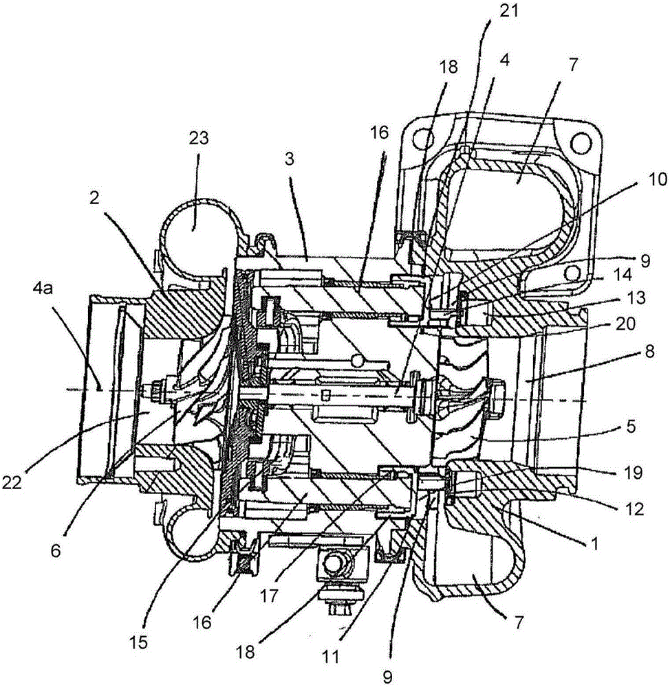
[0038] refer to figure 1 , which shows a known variable geometry turbocharger, wherein the turbocharger comprises a variable geometry turbine housing 1 and a compressor housing 2 interconnected by a central bearing sleeve 3 . The turbocharger shaft 4 extends from the turbine housing 1 to the compressor housing 2 via the bearing sleeve 3 . A turbine wheel 5 is mounted on one end of the shaft 4 for rotation within the turbine housing 1 and a compressor wheel 6 is mounted on the other end of the shaft 4 for rotation within the compressor housing 2 . The shaft 4 rotates about the turbocharger axis 4 a on a bearing assembly located in the bearing housing 3 .

[0039] The turbine housing 1 defines an inlet volute 7 to which gas from an internal combustion engine (not shown) is delivered. Exhaust gas flows from the inlet volute 7 to the axial discharge passage 8 via the annular inlet passage 9 and the turbine wheel 5 . The inlet passage 9 is bounded on one side by a surface 10 of ...


PUM


Abstract

A variable geometry turbine comprising: a housing; a turbine wheel supported in the housing for rotation about a turbine axis; an annular inlet passage upstream of said turbine wheel defined between respective inlet surfaces defined by an annular nozzle ring and a facing annular shroud: the nozzle ring being axial movable to vary the size of the inlet passage; a circumferential array of inlet vanes supported by the nozzle ring and extending across the inlet passage; the shroud covering the opening of a shroud cavity defined by the housing inlet passage and inboard of the shroud, and defining a circumferential array of vane slots, the vane slots and shroud cavity being configured to receive said inlet vanes to accommodate axial movement of the nozzle ring; wherein the annular shroud comprises an outer flange around its radially outer periphery, the outer flange defining a circumferential flange groove for receiving a retaining ring for securing the shroud in the opening of the shroud cavity, the flange groove being defined on an inboard side by a radially extending flange wall; wherein an annular flange rim extends axially inboard from said radial flange wall.

Description

technical field [0001] The present invention relates to a variable geometry turbine. In particular but not exclusively, the invention relates to a variable geometry turbine for a turbocharger or other turbomachine. Background technique [0002] A turbomachine includes a turbine. A conventional turbine includes an exhaust gas driven turbine wheel mounted on a rotatable shaft within a turbine housing connected downstream of the engine outlet manifold. Rotation of the turbine wheel drives a compressor wheel mounted on the other end of a shaft within the compressor housing to deliver compressed air to the engine intake manifold, or a gear that transmits mechanical power to the engine flywheel or crankshaft. Turbine drive shafts are traditionally supported by journal and thrust bearings within bearing housings including appropriate lubrication systems. [0003] A turbocharger is a well known device for supplying air to the intake port of an internal combustion engine at a pres...

Claims


Application Information

Patent Timeline
Patent Type & Authority Patents(China)
IPC IPC(8): F01D17/16
CPCF01D17/14F01D17/167F05D2220/40
Inventor 格伦·L·贝克加里·贝舍尔斯蒂莫西·詹姆斯·威廉·普罗克特尔约翰·弗雷德里克·帕克约翰·迈克尔·拜沃特拉姆·戈卡尔
Owner CUMMINS LTD
Why Eureka
Try Eureka