Ophthalmic lens doublet for ophthalmoscopy

a technology of indirect ophthalmoscopy and ophthalmic lens, which is applied in the field of ophthalmoscopy, can solve the problems of devices that do not find wide application, and achieve the effect of optimizing asphericity and highest possible quality

Active Publication Date: 2019-06-25
FARBEROV ARKADIY
View PDF5 Cites 0 Cited by
  • Summary
  • Abstract
  • Description
  • Claims
  • Application Information

AI Technical Summary

Benefits of technology

[0014]The convex-concave lens element and the convex-convex lens element of the doublet of the invention are coaxial with each other and are used for correction of astigmatism of the eye retina image and for forming an aerial image free of distortions caused by the curvature of the retina.
[0017]Conventionally, optical glasses used in doublets, e.g., in the objectives of microscopes or photo cameras, have greater differences in refractive indices than in the doublet of the invention. It has been found by the inventor that the use of doublets with glasses of component lens elements, even with small differences in refractive indices but with an unusually great difference in spectral dispersion, produces a noticeable synergistic effect manifested in significant improvement of the image quality. For example, resolution of the image (i.e., a number of lines per mm) can be doubled. In a conventional ophthalmic lens, resolution capacity in the field of view center (FOV center) is much higher than the resolution capacity in the periphery of the FOV (i.e., on the edge of the FOV) and the difference between both resolutions is significant. In the ophthalmic doublet of the invention this difference is much smaller. In addition, other properties such as brightness and contrast of the image are also noticeably improved as compared to a conventional ophthalmic lens.

Problems solved by technology

Such devices did not find wide application because of their relatively complicated use.

Method used


Image

  • Ophthalmic lens doublet for ophthalmoscopy
  • Ophthalmic lens doublet for ophthalmoscopy

Examples


Embodiment Construction

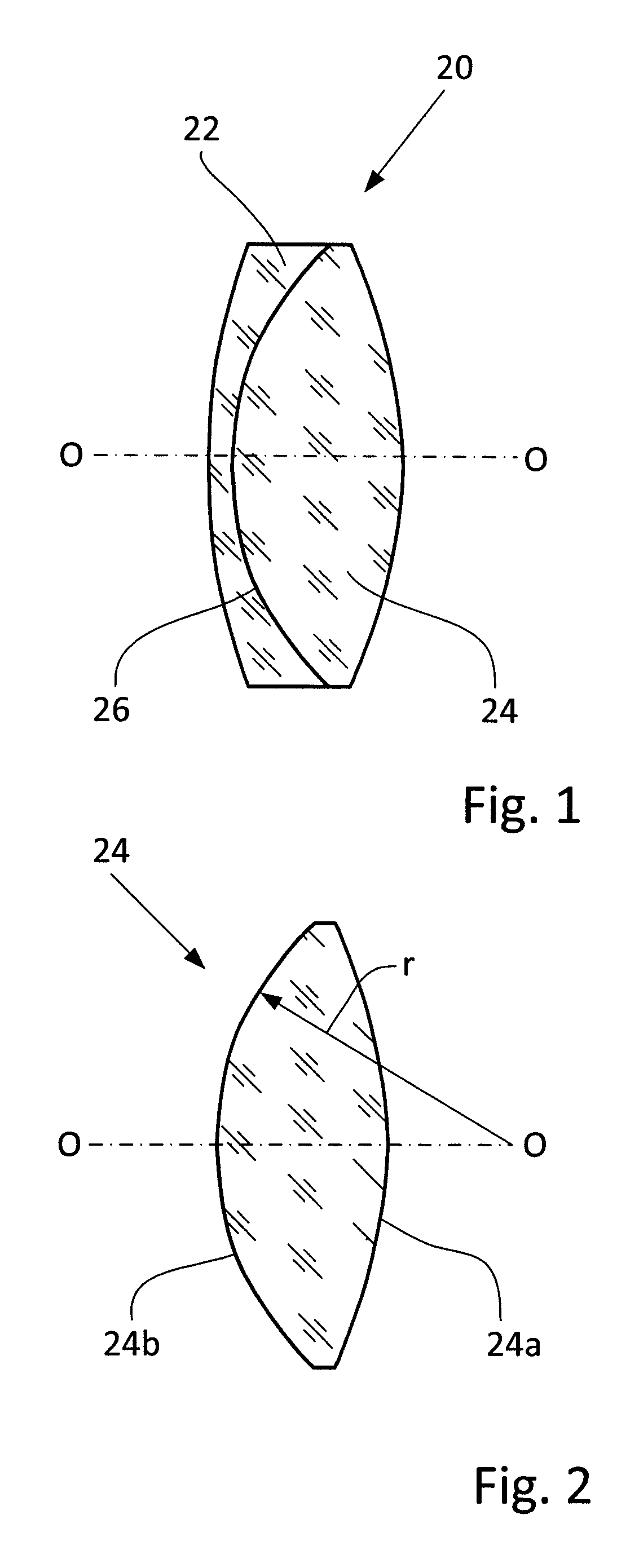
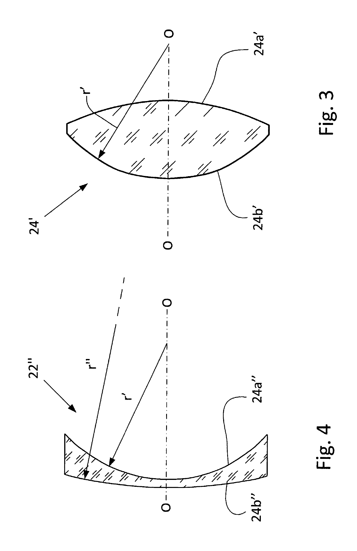
[0023]It is understood that because the size of the patient's retina image on the observer's retina is smaller than the illuminated area of the patient's retina, it seems it would be appropriate to make an ophthalmic lens with the diameter as big as possible. However, such an approach is associated with some problems. More specifically, a large field of view requires adequate image quality correction not only for the central field point but for edges as well. Usually, a conventional ophthalmic lens is a simple lens with spherical surfaces, and the above requirement leads to steep radii. It should be noted that the field of view depends not only on the lens diameter but rather on the focal or working distance of the ophthalmic lens, and the smaller is this distance, the higher is lens dioptricity and the greater the field of view.

[0024]Another reason for which lenses exclusively with spherical surfaces practically do not find use in ophthalmoscopy is that their geometric and chromati...


PUM


Abstract

Proposed is an ophthalmic lens doublet for indirect ophthalmoscopy. The doublet is cemented into an integral unit from two lens elements, of which is a convex-convex lens element and another is a convex-concave lens element. Both lens elements have external and internal surfaces and may be combined so that the ophthalmic lens doublet has asphericity either on one side or on both sides of the unit. The aspheric surface is characterized by asphericity Z of the following formula (1)Z=Y2 / {R+[R2−(1+k)Y2]1 / 2}  (1),where Z is in one of coordinates in a Cartesian coordinate system, Y is a second coordinate in the Cartesian coordinate system, R and k being variable parameters which are different for each selected values of d, where d is an outer diameter of the ophthalmic lens doublet.

Description

FIELD OF THE INVENTION[0001]The present invention relates to the field of ophthalmoscopy, in particular, to an ophthalmic lens doublet for indirect ophthalmoscopy used for observing the fundus and structure in the posterior chamber of a patient's eye.BACKGROUND OF THE INVENTION[0002]Ophthalmic lenses with light sources and dioptricity of 60 D and higher are known as Slit lamp lenses. Ophthalmic lenses with light sources and dioptricity of 40 D and lower are known as BIO lenses. They are used for indirect ophthalmoscopy with slit lamps or a light attached to a headband. In this case, a light source is a headlight, which is secured on the ophthalmologist's head, or a lamp that directs the light directly into the patient's eye via special mirror. The instruments that are used in the latter case are known as ophthalmoscopes.[0003]Ophthalmoscopy is a test intended for observation of the fundus of the eye and other structures of the posterior chamber of an eye. The ophthalmoscopy is an ey...

Claims


Application Information

Patent Timeline
Patent Type & Authority Patents(United States)
IPC IPC(8): A61B3/10G02B3/04A61B3/12G02B3/00
CPCA61B3/1208G02B3/04G02B2003/0093G02B9/02G02B13/18
Inventor FARBEROV, ARKADIY
Owner FARBEROV ARKADIY
Why Eureka
Try Eureka