Image lens system

a technology of image lens and lens body, applied in the field of image lens system, can solve the problems of reducing reducing the degree of freedom in arranging the lens system, and unable to meet optical systems of even higher level, so as to reduce the total track length of the system, improve image quality, and reduce the effect of total track length

Active Publication Date: 2013-03-21
LARGAN PRECISION
View PDF5 Cites 18 Cited by
  • Summary
  • Abstract
  • Description
  • Claims
  • Application Information

AI Technical Summary

Benefits of technology

[0011]By such arrangement, not only the photosensitivity and total track length of the system can be reduced, but also better image quality can be obtained.
[0012]In the aforementioned image lens system, the first lens element has positive refractive power and thereby can provide significant refractive power needed for the system and is favorable for reducing the total track length thereof. When the second lens element has negative refractive power, the aberration produced by the first lens element with positive refractive power can be effectively corrected. When the third lens element has positive refractive power, the sensitivity reduction of the system can be achieved with respect to the positive refractive power of the first lens element. When the fourth lens element has negative refractive power, the principal point of the system can be positioned away from the image plane so that the total track length of the system can be favorably shortened for keeping the system compact.
[0013]In the aforementioned image lens system, the first lens element can be a bi-convex lens element, and thereby the refractive power of the first lens element can be strengthened for reducing the total track length of the system. When the second lens element is a bi-concave lens element, the aberration of the system can be corrected favorably. In addition, when the second lens element has an image-side surface, whose region near the optical axis is concave but the off-axis region thereof is convex, the angle at which light projects onto the image sensor from the off-axis field can be effectively reduced so that the sensing efficiency of the image sensor can be improved and the off-axis aberration can be corrected. Accordingly, the insufficiency of the conventional four-lens-element lens system can be compensated for satisfying the higher demands. When the third lens element has a concave object-side surface and a convex image-side surface, the astigmatism of the system can be favorably corrected. When the fourth lens element has a convex object-side surface and a concave image-side surface, the high order aberration and the astigmatism of the system can be favorably corrected. Furthermore, when at least one inflection is formed on the fourth lens element, the angle at which light projects onto the image sensor from the off-axis field can be effectively reduced so that the sensing efficiency of the image sensor can be improved and the off-axis aberration can be corrected.

Problems solved by technology

Because the progression of manufacturing technology and the trend of being compact for electrical products, the pixel size of sensors is continuously required to be reduced and the demand of the image quality of system is getting higher and higher; therefore, the conventional three-lens-element system can no longer satisfy optical systems of even higher level.
First, the degree of freedom in arranging the lens system is curtailed due to the employment of excessive number of spherical glass lenses; thus, the total track length of the system cannot be reduced easily.
Second, the process of adhering glass lenses together is complicated, posing difficulties in manufacturing.
Moreover, because the size of lens system is getting smaller, multiple reflection of unnecessary light in the lens tube is often caused as such compact lens system is configured in such limited space, and the imaging is also affected.

Method used


Image

  • Image lens system
  • Image lens system
  • Image lens system

Examples


embodiment 1

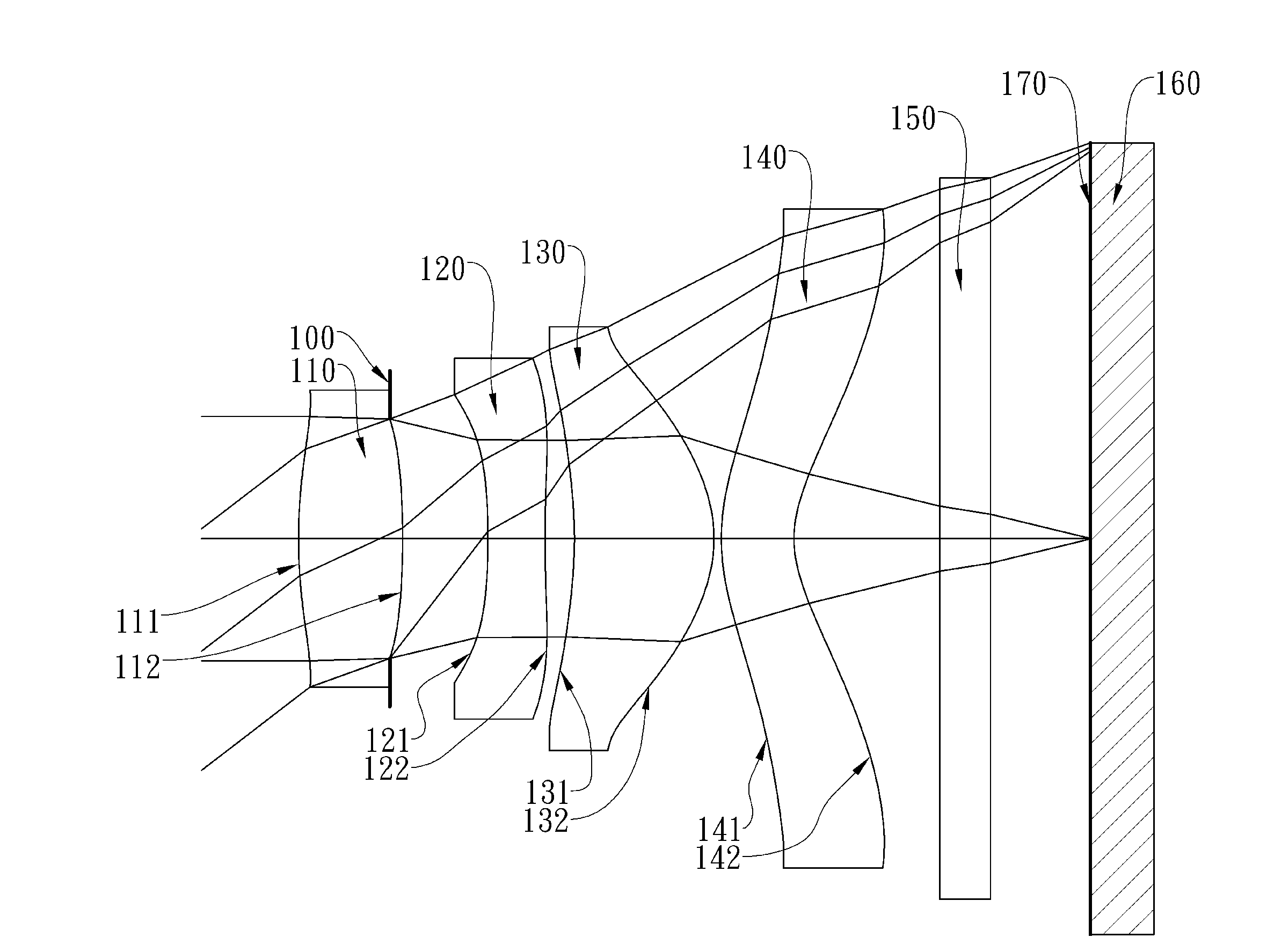
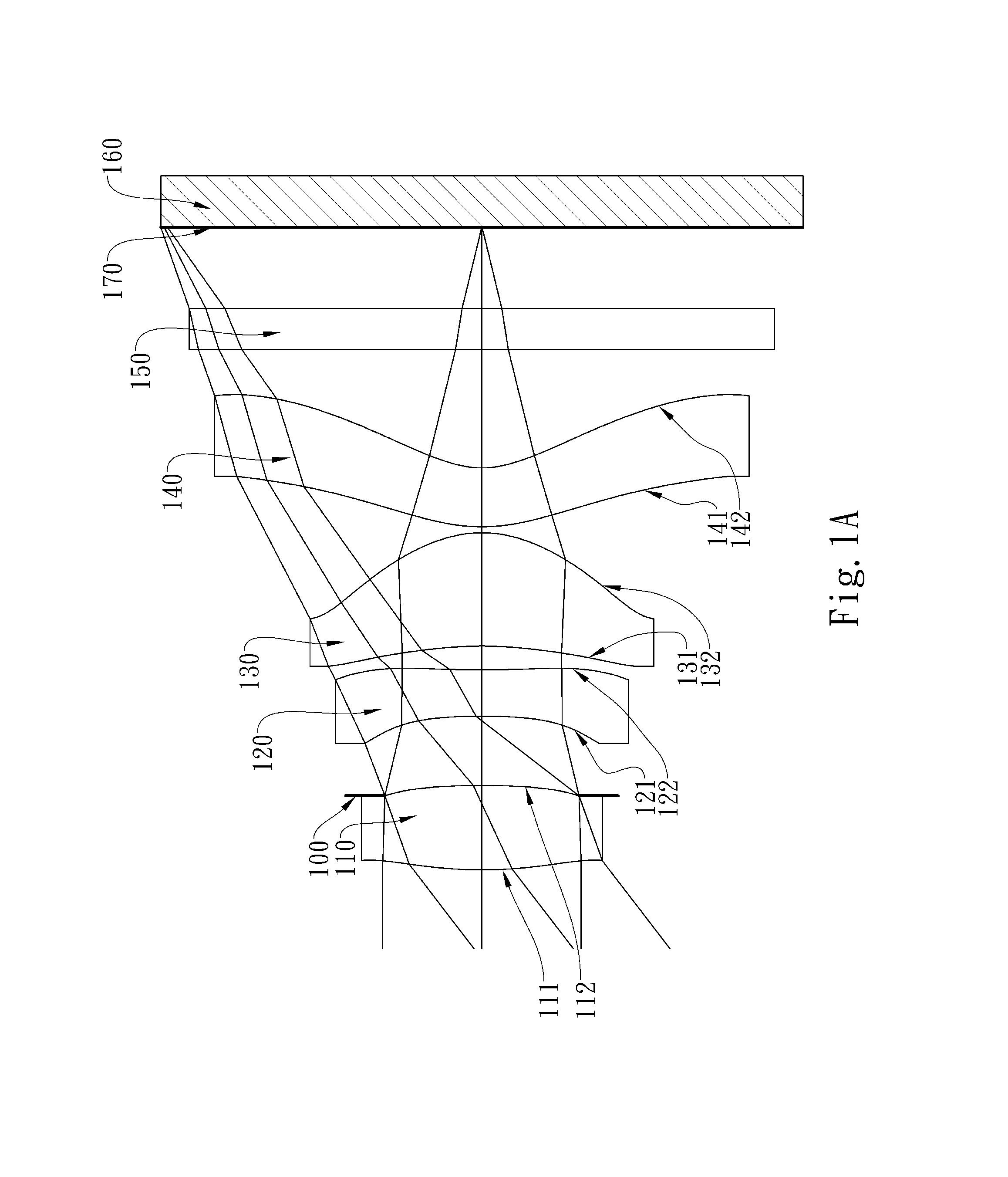
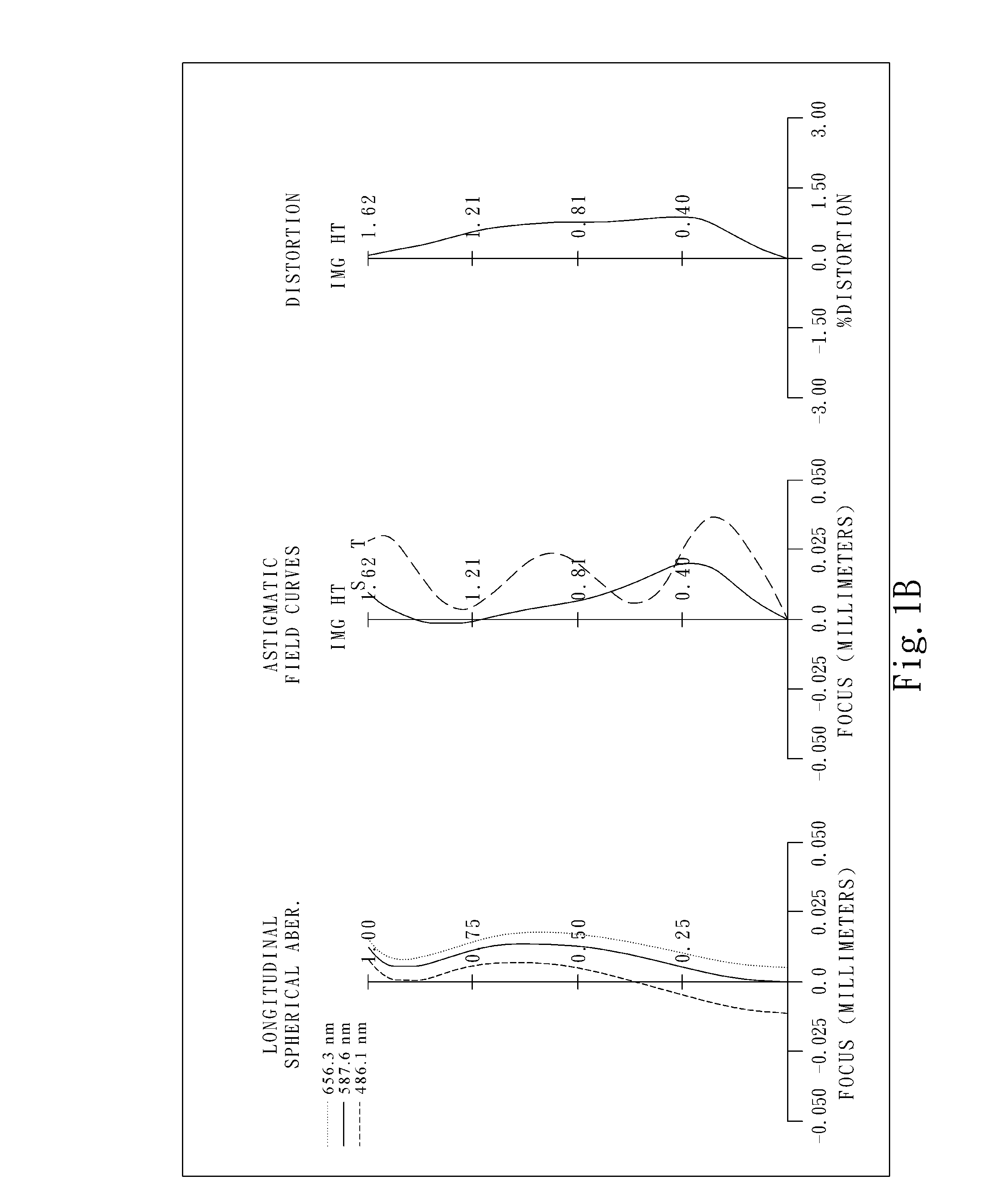
[0063]FIG. 1A shows an image lens system in accordance with the first embodiment of the present invention, and FIG. 1B shows the aberration curves of the first embodiment of the present invention. The image lens system of the first embodiment of the present invention comprises four lens elements, in order from an object side to an image side:

[0064]a first lens element 110 made of plastic with positive refractive power having a convex object-side surface 111 and a convex image-side surface 112, the object-side and image-side surfaces 111 and 112 thereof being aspheric;

[0065]a second lens element 120 made of plastic with negative refractive power having a concave object-side surface 121 and a concave image-side surface 122 near the optical axis, the object-side and image-side surfaces 121 and 122 thereof being aspheric; moreover, the off-axis region of the image-side surface 122 is changed to be convex;

[0066]a third lens element 130 made of plastic with positive refractive power havin...

embodiment 2

[0095]FIG. 2A shows an image lens system in accordance with the second embodiment of the present invention, and FIG. 2B shows the aberration curves of the second embodiment of the present invention. The image lens system of the second embodiment of the present invention comprises four lens elements, in order from an object side to an image side:

[0096]a first lens element 210 made of plastic with positive refractive power having a convex object-side surface 211 and a convex image-side surface 212, the object-side and image-side surfaces 211 and 212 thereof being aspheric;

[0097]a second lens element 220 made of plastic with negative refractive power having a concave object-side surface 221 and a concave image-side surface 222, the object-side and image-side surfaces 221 and 222 thereof being aspheric; moreover, the off-axis region of the image-side surface 222 is changed to be convex;

[0098]a third lens element 230 made of plastic with positive refractive power having a concave object-...

embodiment 3

[0104]FIG. 3A shows an image lens system in accordance with the third embodiment of the present invention, and FIG. 3B shows the aberration curves of the third embodiment of the present invention. The image lens system of the third embodiment of the present invention comprises four lens elements, in order from an object side to an image side:

[0105]a first lens element 310 made of plastic with positive refractive power having a convex object-side surface 311 and a convex image-side surface 312, the object-side and image-side surfaces 311 and 312 thereof being aspheric;

[0106]a second lens element 320 made of plastic with negative refractive power having a concave object-side surface 321 and a concave image-side surface 322 near the optical axis, the object-side and image-side surfaces 321 and 322 thereof being aspheric; moreover, the off-axis region of the image-side surface 322 is changed to be convex;

[0107]a third lens element 330 made of plastic with positive refractive power havin...


PUM


Abstract

This invention provides an image lens system comprising: a first lens element with positive refractive power; a second lens element with negative refractive power having a concave object-side surface and a concave image-side surface, both the object-side and image-side surfaces thereof being aspheric and made of plastic; a third lens element with positive refractive power; and a fourth lens element with negative refractive power, and at least one inflection point is formed on at least one of the object-side and image-side surfaces thereof; wherein, the region of the image-side surface of the second lens element near the optical axis is concave, but the off-axis region thereof is convex. By such arrangement, not only the photosensitivity and total track length of the system can be reduced, but also better image quality can be obtained.

Description

CROSS-REFERENCE TO RELATED APPLICATIONS[0001]This non-provisional application claims priority under 35 U.S.C. §119(a) on Patent Application No. 100133706 filed in Taiwan, R.O.C. on Sep. 20, 2011, the entire contents of which are hereby incorporated by reference.BACKGROUND OF THE INVENTION[0002]1. Field of the Invention[0003]The present invention relates to an image lens system, and more particularly, to a compact image lens system used in electronic products.[0004]2. Description of the Prior Art[0005]In recent years, with the popularity of portable electronic products having photographing function, the demand of compact imaging lens system has grown. Generally, the sensor of a general photographing camera is none other than CCD (Charge Coupled Device) or CMOS device (Complementary Metal Oxide Semiconductor device). Furthermore, advances in semiconductor manufacturing technology have allowed the pixel size of sensors to be reduced and therefore lead compact imaging lens systems to hi...

Claims


Application Information

Patent Timeline
Patent Type & Authority Applications(United States)
IPC IPC(8): G02B13/18
CPCG02B13/004G02B9/34
Inventor TANG, HSIANG-CHIHSU, PO-LUNCHOU, MING-TA
Owner LARGAN PRECISION
Why Eureka
Try Eureka