Spark plug and production method therefor

a technology of spark plugs and plugs, which is applied in the manufacture of spark plugs, spark plugs, electrical equipment, etc., can solve the problems of ground electrode wear and proceed, and achieve the joint strength, spark wear resistance of the tip, and joint strength.

Active Publication Date: 2019-07-30
NGK SPARK PLUG CO LTD
View PDF19 Cites 0 Cited by
  • Summary
  • Abstract
  • Description
  • Claims
  • Application Information

AI Technical Summary

Benefits of technology

[0005]The present invention addresses the above problem. An advantage of the present invention is a spark plug that has a ground electrode with a tip joined thereto and combines the joint strength of the tip with the spark wear resistance of the ground electrode.
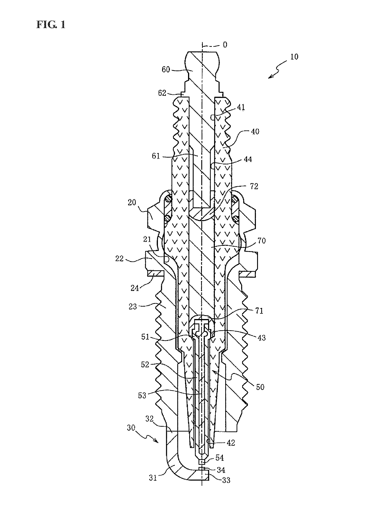
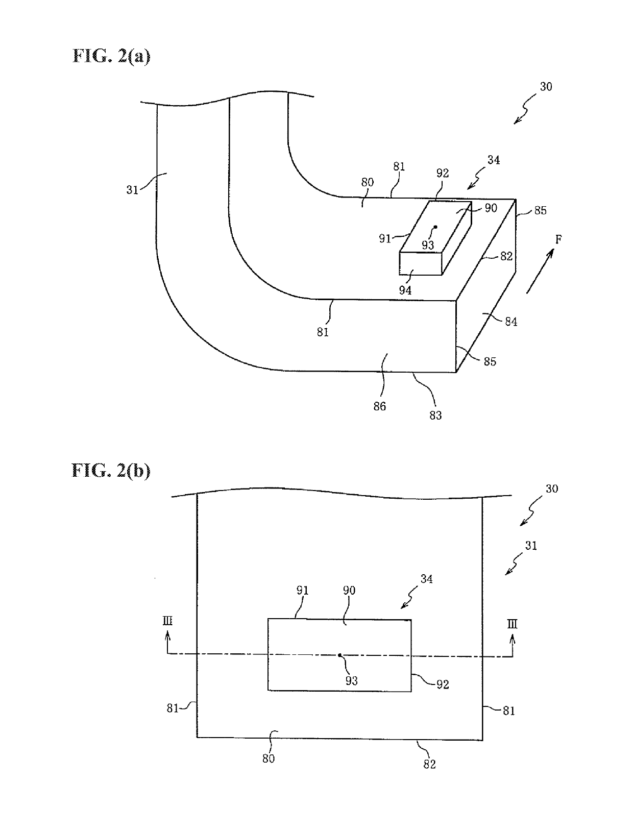
[0006]In accordance with a first aspect of the present invention, there is provided a spark plug comprising: a metal shell; a center electrode held insulatedly in the metal shell; and a ground electrode that includes an electrode base having a facing surface facing the center electrode and a tip containing a noble metal and arranged on the facing surface of the electrode base. The electrode base is joined at a first end portion thereof to the metal shell. The electrode base has: an opposite surface located opposite the facing surface; an end surface connecting the opposite surface and the facing surface at a second end portion of the electrode base opposite the first end portion; and a pair of side surfaces continuing to the end surface via sides of the second end portion and connecting the opposite surface and the facing surface. The tip has: a top surface facing the center electrode; and a bottom surface located opposite the top surface and joined to the electrode base with a weld zone formed therebetween.
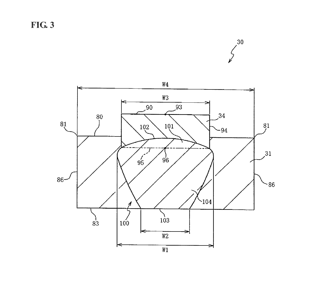
[0007]The weld zone includes: a back region exposed at the opposite surface of the electrode base; a joint region at which the tip is joined; and a connection region connecting the joint region and the back region in a thickness direction of the electrode base without being exposed at the side surfaces of the electrode base. In a cross section of the ground electrode taken through the side surfaces of the electrode base along a plane passing through the centers of the top and bottom surfaces of the tip, a value of a width of the top surface of the tip being divided by a width of the facing surface of the electrode base is greater than 0.3 so that the top surface of the tip at which spark discharge is likely to occur is made relatively large in width. Further, a maximum width of the connection region in a direction perpendicular to the thickness direction of the electrode base is larger than a width of the back region. It is thus possible to ensure the joint area of the joint region and thereby attain the joint strength of the tip. As the exposed back region of the weld zone is present at the opposite surface of the electrode base at which spark discharge is unlikely to occur, it is possible to attain the spark wear resistance of the ground electrode. Accordingly, the spark plug combines both the joint strength of the tip and the spark wear resistance of the ground electrode.
[0008]In accordance with a second aspect of the present invention, there is provided a spark plug as described above, wherein, in the cross section, an interface of the joint region with the tip is convex toward the top surface. In this invention, the joint strength is attained at a center portion of the tip. The spark wear resistance of the tip is also attained by ensuring the distance from the bottom surface to the top surface at a peripheral portion of the tip. It is thus possible to combine the joint strength and spark wear resistance of the tip in addition to achieving the effects of the invention of claim 1.
[0009]In accordance with a third aspect of the present invention, there is provided a spark plug as described above, wherein, in the cross section, the bottom surface of the tip is located closer to the opposite surface than the facing surface of the electrode base, and the joint region is located closer to the opposite surface than the facing surface of the electrode base without being exposed at the facing surface of the electrode base. It is possible in this invention to prevent the joint region from serving as a starting point of spark wear, in addition to achieving the effects of the invention of claim 1 or 2.
[0010]In accordance with a fourth aspect of the present invention, there is provided a spark plug as described above, wherein the facing surface of the electrode base has base long sides bordering the side surfaces and a base short side bordering the end surface and being shorter than the base long sides, wherein the top surface of the tip has a long side and a short side, and wherein the tip is arranged on the facing surface, with the short side of the tip being along the base long side and the long side of the tip being along the base short side. When the spark plug is mounted to an internal combustion engine, a spark discharge is blown off due to the occurrence of gas flow in a combustion chamber of the internal combustion engine along a direction of the base short side of the facing surface of the electrode base. In this invention, however, the long side of the tip is aligned along such a direction so that the spark discharge can be prevented from occurring on the electrode base. It is thus possible to suppress spark wear of the electrode base in addition to achieving the effects of the invention of any of claims 1 to 3.

Problems solved by technology

This makes it likely that wear of the ground electrode will proceed.

Method used


Image

  • Spark plug and production method therefor
  • Spark plug and production method therefor
  • Spark plug and production method therefor

Examples


examples

[0073]The present invention will be described in more detail below by way of the following examples. It should be noted that the following explanations are illustrative and are not intended to limit the present invention thereto.

example

[0074]Various types of ground electrodes 30 were obtained by providing electrode bases 31 as explained above in the first embodiment and joining various tips 34 to the respective electrode bases 31. The length of the long sides 91 of the tip 34 was different from one type to another, thereby setting different values (W3 / W4) of the width W3 of the top surface 90 of the tip 34 divided by the width W4 of the facing surface 80 of the electrode base 31. In each ground electrode, the tip 34 was laser welded to the electrode base 31 by emitting and scanning the laser light onto the opposite surface 83 of the electrode base 31 in such manner that loci of the beam axis 113 of the laser light intersected at a position facing the opposite surface 83 of the electrode base 31 as explained in the first embodiment. Herein, 30 samples (ground electrodes) for each value (W3 / W4) were provided.


PUM


Abstract

Disclosed is a spark plug having a ground electrode in which a weld zone is formed a tip and electrode base. The weld zone has: a back region exposed at an opposite surface of the electrode base; a joint region at which the tip is joined; and a connection region connects the joint region and the back region without being exposed at side surfaces of the electrode base. In a cross section of the ground electrode taken through the side surfaces of the electrode base along a plane passing through the centers of the top and bottom surfaces of the tip, a value of a width of the top surface of the tip being divided by a width of the facing surface of the electrode base is greater than 0.3, and a maximum width of the connection region is larger than a width of the back region.

Description

RELATED APPLICATIONS[0001]This application is a National Stage of International Application No. PCT / JP17 / 01052 filed Jan. 13, 2017, which claims the benefit of Japanese Patent Application No. 2016-103310, filed May 24, 2016, the entire contents of which are incorporated herein by reference.FIELD OF THE INVENTION[0002]The present invention relates to a spark plug and a production method therefor. More particularly, the present invention relates to a spark plug having a ground electrode with improved spark wear resistance and a production method therefor.BACKGROUND OF THE INVENTION[0003]There is known a spark plug in which a tip containing a noble metal is joined to a center electrode-facing surface of an electrode base of a ground electrode so as to improve the spark wear resistance of the ground electrode. For example, Japanese Laid-Open Patent Publication No. 2000-40577 discloses a technique of joining a tip to an electrode base by forming a weld zone from a surface of the electrod...

Claims


Application Information

Patent Timeline
Patent Type & Authority Patents(United States)
IPC IPC(8): H01T13/32H01T21/02H01T13/39
CPCH01T13/32H01T21/02H01T13/39H01T13/20
Inventor KAWASHIMA, YUSUKEHAZAMA, HIROYUKI
Owner NGK SPARK PLUG CO LTD
Why Eureka
Try Eureka