[0006]The present invention relates to improvements in the flood barrier panels of the type referred to above which incorporates numerous improvements to facilitate the installation and removal of the barrier panel and to provide more effective sealing of the opening when the barrier is installed for flood protection.
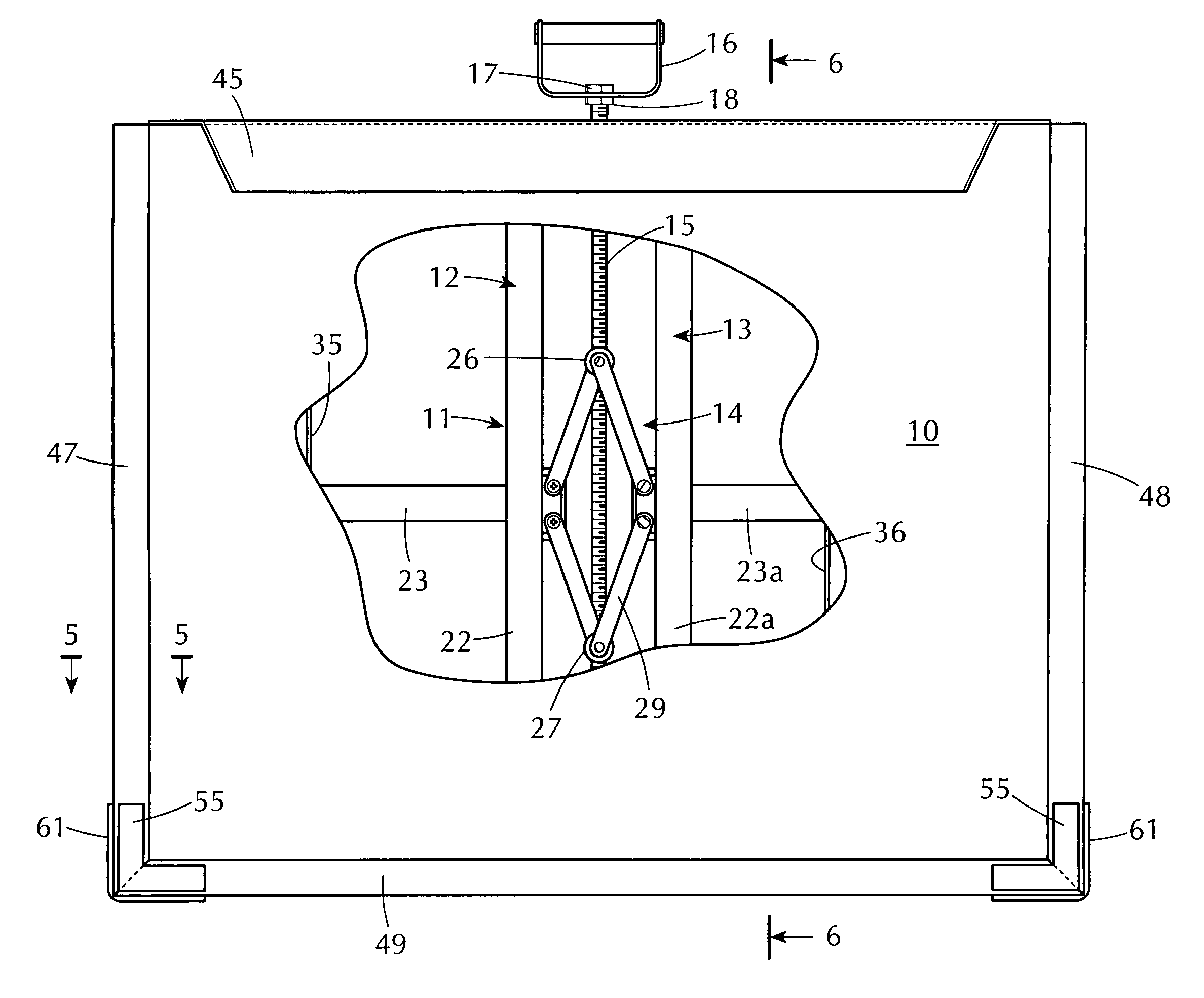
[0007]Pursuant to one aspect of the invention, the laterally adjustable frame is designed such that the elements of the frame are generally symmetrical, and an adjustment linkage is provided centrally in the framework, connected to the opposite sides thereof and operated by a vertical threaded shaft extending through an upper element of the frame and projecting upwardly somewhat beyond the top of the frame. A carrying
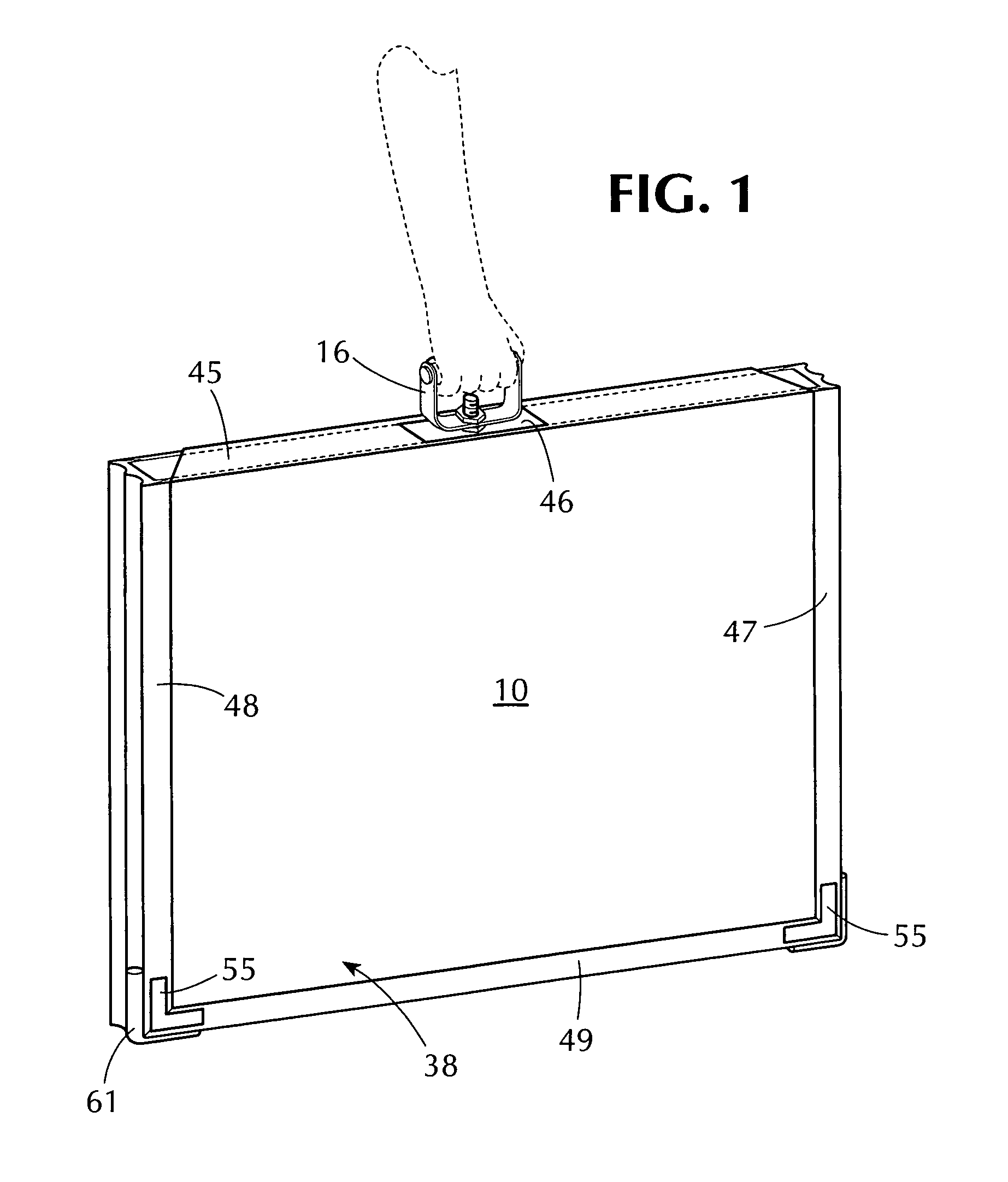
handle is fixed to the upper end of the threaded shaft and serves both as a convenient means for carrying the panel and as a lever for rotating the threaded shaft to achieve expansion and contraction of the barrier frame. This has two important advantages: First, it provides for significantly greater efficiencies in carrying the barrier panel to the desired site and installing it. Second, it allows the frame to be adjusted from within the extensible envelope, while enabling the envelope to have a fold-over flap at the top to prevent the envelope from slipping off of the frame when the frame is in a retracted configuration. The carrying
handle advantageously is removably attached to the threaded shaft, such that it can be removed, when necessary, as when the barrier panel is installed tightly adjacent a door surface, for example, which may interfere with the swinging of the handle for adjusting the framework. In such cases, the handle is removed and a
wrench or the like is used to rotate the threaded shaft to effect the desired width adjustment.
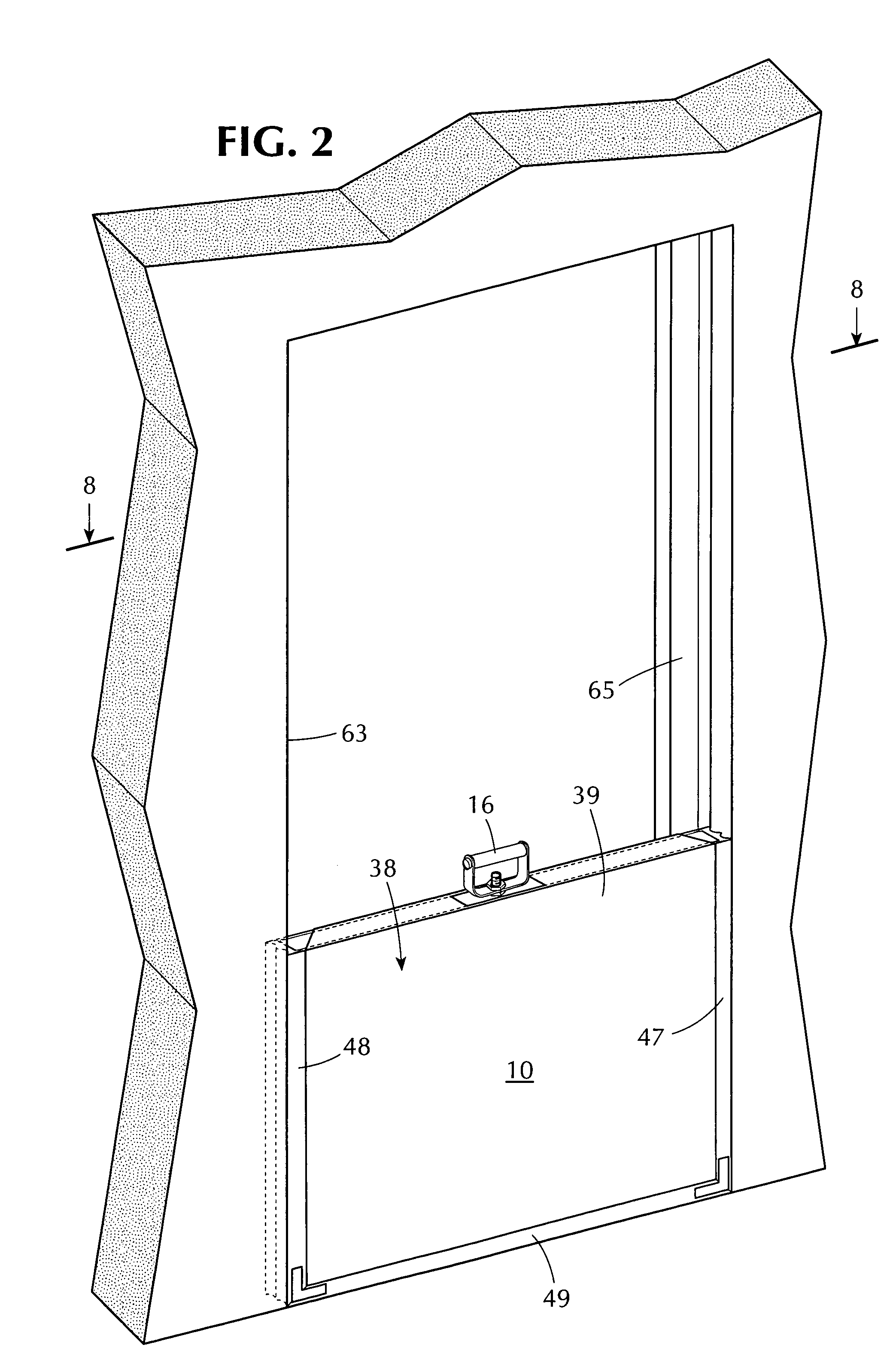
[0008]The barrier panel of the invention also includes an improved and advantageous form of edge seal, which is secured along side and bottom edges of the extensible envelope and provides for tight sealing around the perimeter of the opening to be sealed, accommodating imperfections in the straightness of the perimeter elements. The edge seal advantageously is formed with side flanges which are splayed slightly outward in their normal configuration and spread laterally when subjected to pressure during the installation of the panel in the door or
window opening. The arrangement is such that the pressure of the water against the outer flanges tends to press them tighter against the adjacent supporting surface, to enhance the sealing action of the perimeter seal. Improvements are also made for sealing the lower corner extremes of the barrier panels, which historically have been the most difficult areas to effect a complete seal. In the device of the invention, the perimeter seal is miter
cut at the corners to provide a severe right angle configuration without
rounding, and, in addition, soft foam inserts are provided in grooves in the perimeter seal, at the corner extremities, to further enhance the sealing capabilities at such corner extremities.
[0009]A further advantageous feature of the invention resides in the provision of a guard panel on an outer face of the adjustable frame, arranged to cover the expansion mechanism and threaded operating shaft in all positions of the frame. In this respect, when the elastic envelope in which the frame is received is exposed to the pressure of a head of
flood water, the elastic material may become distended inwardly in open areas between elements of the adjustable frame. If permitted to extend inwardly into contact with elements of the expansion mechanism, it may prevent adjustment of such mechanism when the panel is under load and / or cause damage to the elastic material. To avoid any such problems, a flat sheet
metal panel is affixed to one side of the adjustable frame and extends laterally over to the opposite frame, in all adjustable positions of the frame. The extensible envelope is thus fully supported in the critical areas by the guard panel and cannot become involved in contact with the expansion mechanism.
[0010]In one form of the invention, in which the opening to be sealed is of substantial width, a central supporting
mullion is provided, which is secured to the floor and engages central regions of the barrier panel. The
mullion not only resists inward forces against the panel, resulting from the pressure of flood waters, but also serves to press the center portions of the panel downward tightly against the floor surface to enhance the sealing action in the center portion of the panel. For openings of even larger width, the
mullion may be interposed between two separate panels, such that the two panels are tightened laterally against the center mullion. Advantageously, the mullions are removably attached to the floor, by bolts, for example, such that they can be easily installed when needed and removed between flooding episodes.

