Spiral membrane element and method of manufacturing the same

a spiral membrane element and spiral membrane technology, applied in the field can solve the problems of reducing the separation reducing the permeation performance of spiral membrane elements, and less effective side passage materials, so as to reduce the width of sealing portions, suppress the effect of any increase in manufacturing cost and reducing the loss of pressure per uni

Inactive Publication Date: 2005-04-14
NITTO DENKO CORP
View PDF5 Cites 50 Cited by
  • Summary
  • Abstract
  • Description
  • Claims
  • Application Information

AI Technical Summary

Benefits of technology

[0014] The reduction in width of the sealing portions also makes it possible to reduce any pressure loss per unit effective surface area of the spiral membrane element and suppress any increase in the cost of manufacture, since there is no increase of materials to be used, while also reducing any waste, since there is a decrease of the part removed by trimming.
[0015] The adhesive is preferably a thixotropic fluid. It is often unavoidable due to work arrangements that the adhesive applied to the edges of the separation membrane is left to stand for a certain period of time until the membrane, etc., are wound around the central tube, and on that occasion, any ordinary adhesive spreads by its own weight and forms a sealing portion having a large width. On the other hand, a thixotropic fluid, which has the property of becoming lower in viscosity when given an external force, easily remains in its state as applied if not given any external force after application, so that it facilitates the formation of a sealing portion having a controlled width.
[0016] The separation membrane bonded adhesively on the sealing portions at both ends preferably has the pores of its porous layer closed. The separation membrane usually has a porous structure and allows a fluid to flow in both directions perpendicular and parallel to the membrane. It is however only when the fluid flows in the direction perpendicular to the separation membrane that the membrane exhibits its separation performance. It is therefore necessary to suppress any fluid flow parallel to the separation membrane in the spiral membrane element. It is however sometimes impossible for any adhesive applied to the edges of the separation membrane to suppress any parallel fluid flow completely, and it is sometimes necessary to enlarge the width of each sealing portion, thereby increasing the length of any parallel fluid flow passage and creating a higher resistance to any parallel fluid flow, and as a result it suppresses flow in a parallel direction. Under these circumstances, the closure of the pores in the porous layer of each adhesive-coated portion of the separation membrane as stated above makes it possible to suppress any fluid flow parallel to the membrane and thereby reduce the width of each sealing portion.
[0017] The method of manufacturing a spiral membrane element according to the present invention comprises the steps of spirally winding a separation membrane, a feed-side passage material and a permeation-side passage material in a laminate state around a perforated central tube to form a cylindrically wound body, and forming a sealing portion for preventing a feed-side fluid and a permeation-side fluid from being mixed together, wherein the sealing portion is formed with a substantially constant width by an adhesive in the vicinity of each of both ends of the cylindrically wound body and has 20 to 60% of its width cut off.
[0018] The manufacturing method of the present invention makes it possible to obtain a spiral membrane element having a small width along each sealing portion, while maintaining its sealing property at both ends, and having a large effective membrane surface area without having its separation performance lowered, since it does not initially has any sealing portion having a small width, but a part of each sealing portion is cut off after sealing.

Problems solved by technology

The former method, however, makes the feed-side passage material less effective for stirring the feed-side fluid to prevent concentration polarization in the vicinity of the separation membrane and lowers the separation performance of the spiral membrane element.
The latter method enables the spiral membrane element to be packed with only a smaller amount of separation membranes and lowers its permeation performance.
The cylindrically wound body is, however, spirally sealed (such as adhesion) along a certain width toward both ends thereof, and unless each such sealing portion has at least a certain axial width, it has been impossible to make any reliable sealing and it has been impossible to keep any ineffective membrane surface area below a certain size even if the axial length of the cylindrically wound body may be close to the length of the central tube.

Method used


Image

  • Spiral membrane element and method of manufacturing the same
  • Spiral membrane element and method of manufacturing the same
  • Spiral membrane element and method of manufacturing the same

Examples


example 1

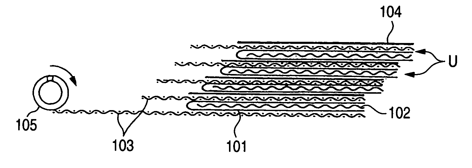
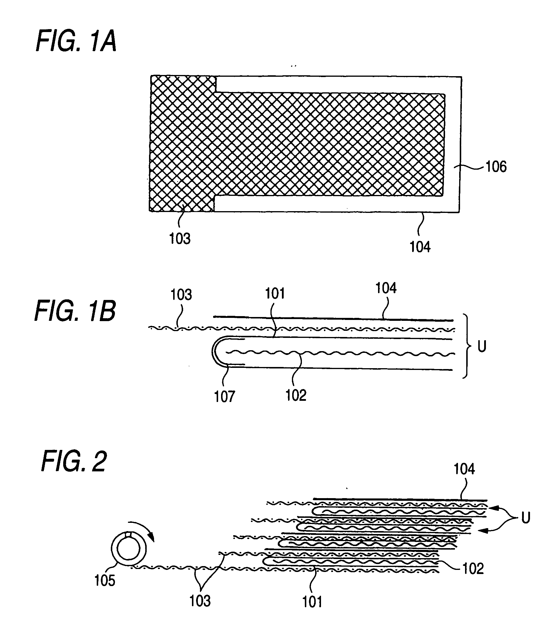
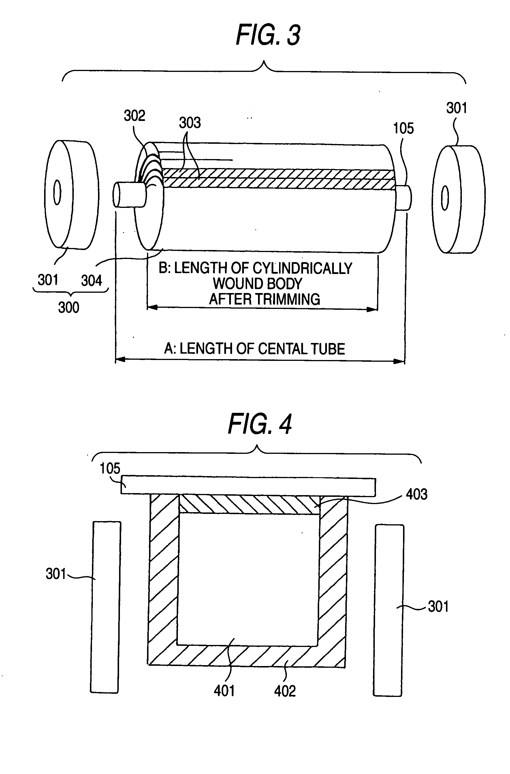
[0060] A spiral membrane element was fabricated in accordance with the manufacturing method of the present invention employing length of a central tube: 1,016 mm, length of a cylindrically wound body after trimming: 975 mm, width of an adhesive-sealed portion (adjacent to each trimmed portion): 15 mm, width of an adhesive-sealed portion (adjacent to the final end of a separation membrane): 25 mm, width of a protective tape: 25 mm, separation membrane: NTR-759HR (product of Nitto Denko Corporation), length of the separation membrane: 1,460 mm, width of the separation membrane: 1016 mm, the number of separation membrane units: 26, thickness of a feed-side passage material: 0.72 mm, and angle of intersections of a net of the feed-side passage material: 90°. An adhesive used was a thixotropic adhesive (UR-3501, product of H.B. Fuller Japan Co., Ltd.). Portions of the separation membrane to which the adhesive will be applied had the pores of their porous layers closed by melting under he...


PUM

PropertyMeasurementUnit
thicknessaaaaaaaaaa
widthaaaaaaaaaa
widthaaaaaaaaaa

Abstract

A spiral membrane element having an enlarged effective membrane surface area without having its separation performance lowered, while maintaining the sealing property of any sealing portion of a cylindrically wound body, and a manufacturing method of the same are disclosed. The spiral membrane element includes a cylindrically wound body comprising a perforated central tube and, spirally wound therearound, a separation membrane, a feed-side passage material and a permeation-side passage material in a laminated state, and a sealing portion for preventing a feed-side fluid and a permeation-side fluid from being mixed together, wherein the sealing portion formed at each of both ends of the cylindrically wound body is spirally formed with a substantially constant width by an adhesive and has a trimmed section formed on its whole end surface, and the cylindrically wound body has a ratio of its length to the length of the central tube of 0.96 to 1.00, and a ratio of an ineffective membrane surface area to the entire membrane surface area of 0.02 to 0.10.

Description

FIELD OF THE INVENTION [0001] This invention relates to a spiral membrane element comprising a cylindrically wound body comprising a perforated central tube and, spirally wound therearound, a separation membrane, a feed-side passage material and a permeation-side passage material in a laminated state, and a sealing portion for preventing a feed-side fluid and a permeation-side fluid from being mixed together. BACKGROUND ART [0002] As a fluid separation element used in reverse osmosis, ultrafiltration, microfiltration, gas permeation, degassing, etc., there is known, for example, a spiral fluid separation element comprising a central tube and, spirally wound therearound, a unit comprising a feed-side passage material guiding a feed-side fluid to the surface of a separation membrane, the separation membrane separating the feed-side fluid, and a permeation-side passage material guiding to the central tube a permeation-side fluid separated from the feed-side fluid by permeating through ...

Claims


Application Information

Patent Timeline
Patent Type & Authority Applications(United States)
IPC IPC(8): B01D63/00B01D63/08B01D63/10B01D65/00
CPCB01D65/003B01D63/10
Inventor ISHII, KATSUMI
Owner NITTO DENKO CORP
Why Eureka
Try Eureka