Dust separating apparatus

a technology of dust separation apparatus and dust collection, which is applied in the direction of dispersed particle separation, centrifuges, separation processes, etc., can solve the problems of low dust collection efficiency, increased vacuum cleaner size, so as to increase the collection efficiency and compact the effect of siz

Inactive Publication Date: 2007-08-02
SAMSUNG GWANGJU ELECTRONICS CO LTD
View PDF13 Cites 49 Cited by
  • Summary
  • Abstract
  • Description
  • Claims
  • Application Information

AI Technical Summary

Benefits of technology

[0009]The present disclosure has been developed in order to overcome the above drawbacks and other problems associated with the conventional arrangement. An aspect of the present disclosure is to provide a dust separating apparatus using centrifugal force that increases the collecting efficiency for fine dust and has a compact size.

Problems solved by technology

However, the conventional dust separating apparatus has a problem that fine dust having a weight substantially similar to that of the air is likely to pass through the filter to the vacuum motor so that the collecting efficiency for fine dust is low.
However, when using the additional dust-collecting member, the vacuum cleaner needs a separate space in which the additional dust-collecting member is disposed so that the size of the vacuum cleaner is increased.
As a result, the size of the vacuum cleaner is increased.

Method used


Image

  • Dust separating apparatus
  • Dust separating apparatus
  • Dust separating apparatus

Examples


Embodiment Construction

[0023]Hereinafter, certain exemplary embodiments of the present disclosure will be described in detail with reference to the accompanying drawings.

[0024]The matters defined in the description, such as a detailed construction and elements thereof, are provided to assist in a comprehensive understanding of the disclosure. Thus, it is apparent that the present disclosure may be carried out without those defined matters. Also, well-known functions or constructions are omitted to provide a clear and concise description of exemplary embodiments of the present disclosure.

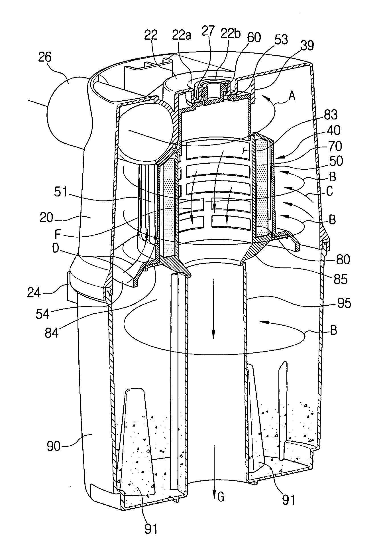
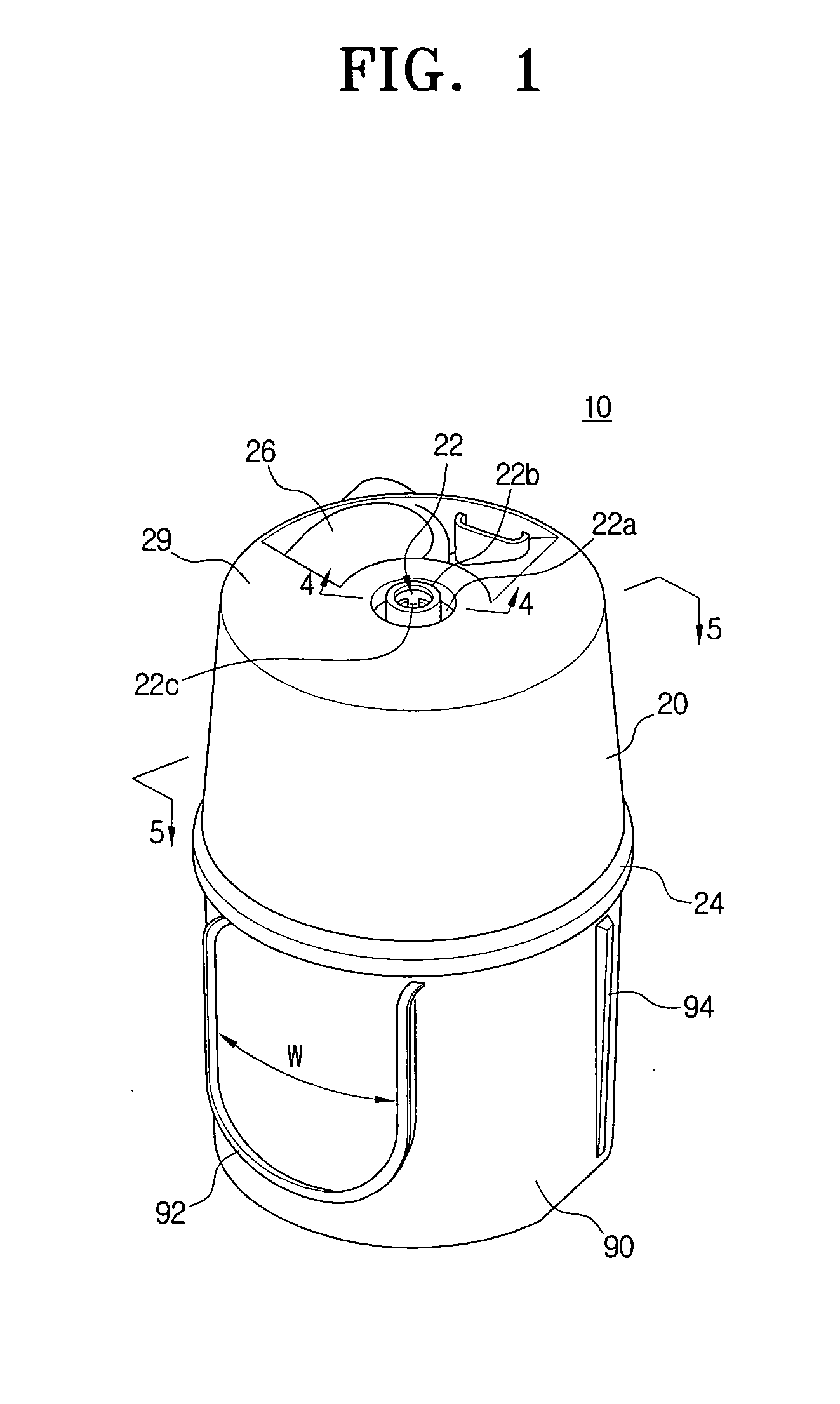
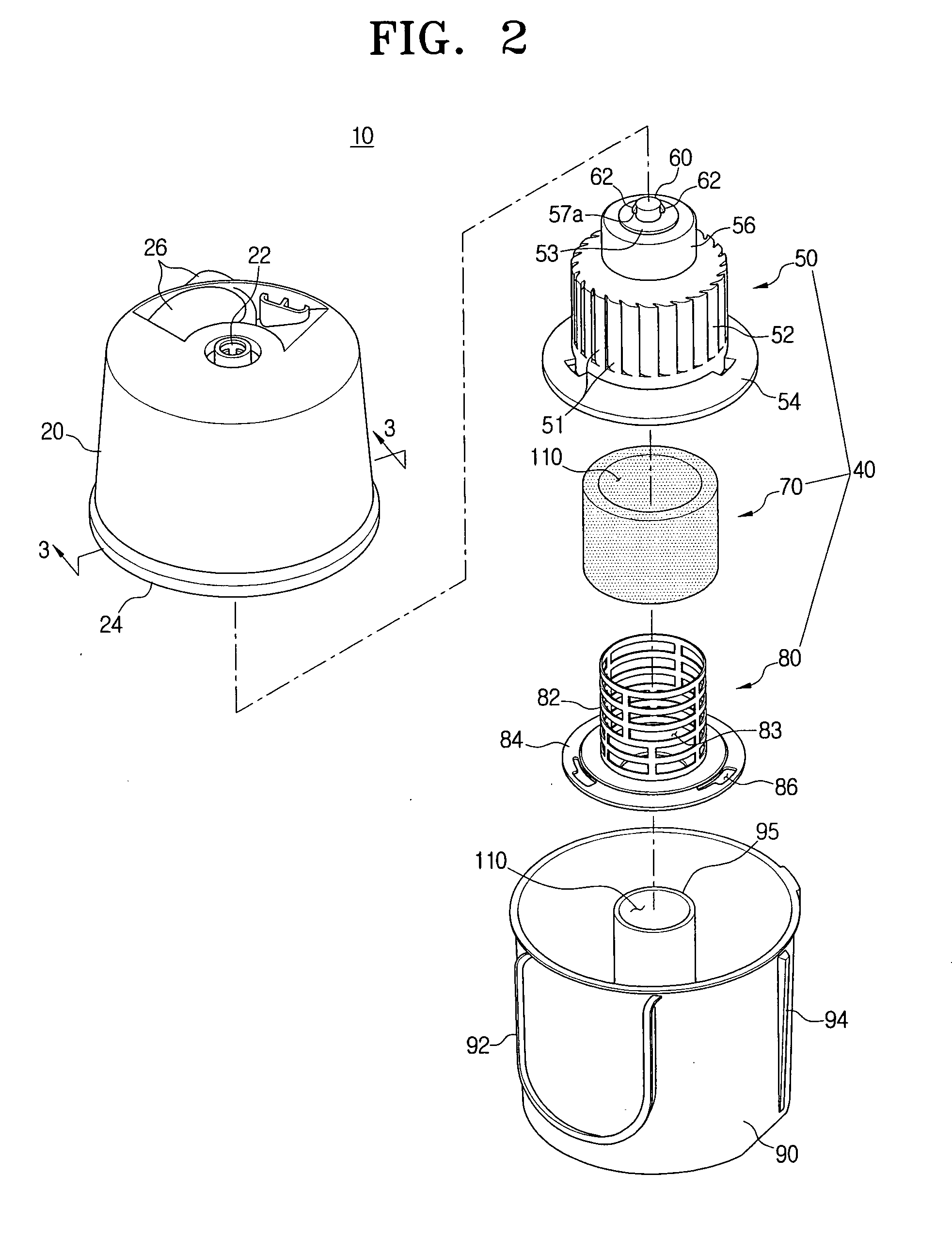
[0025]FIG. 1 is a perspective view illustrating a dust separating apparatus according to an embodiment of the present disclosure, and FIG. 2 is an exploded perspective view illustrating the dust separating apparatus of FIG. 1.

[0026]Referring to FIGS. 1 and 2, a dust separating apparatus 10 according to an embodiment of the present disclosure includes a cyclone body 20, a dust collecting receptacle 90, and a filter unit 40....


PUM

PropertyMeasurementUnit
widthaaaaaaaaaa
centrifugal forceaaaaaaaaaa
cylindrical shapeaaaaaaaaaa

Abstract

The present disclosure relates to a dust separating apparatus using a centrifugal force. The dust separating apparatus includes a cyclone body configured to separate dust from air using centrifugal force, and having an entering pipe through which the air enters; a dust collecting receptacle configured to be detachably connected to a bottom end of the cyclone body, and for collecting dust separated from the air; and a filter unit configured to be detachably disposed to the cyclone body, wherein the filter unit has a compact, at least double structure formed by a filter for filtering large dust and a filter for filtering fine dust.

Description

CROSS-REFERENCE TO RELATED APPLICATIONS[0001]This application claims the benefit under 35 U.S.C. § 119 from U.S. Provisional Application No. 60 / 762,933 filed Jan. 27, 2006 in the United States Patent & Trademark Office, and claims the benefit under 35 U.S.C. § 119 from Korean Patent Application No. 2006-26863 filed Mar. 24, 2006 in the Korean Intellectual Property Office, the disclosures of both of which are incorporated herein by reference in their entirety.BACKGROUND OF THE INVENTION[0002]1. Field of the Invention[0003]The present disclosure relates to a dust separating apparatus. More particularly, the present disclosure relates to a dust separating apparatus that causes air containing dust and / or contaminant particles to enter and to whirl so as to separate the dust and contaminant particles from the entering air, and has a filter unit filtering dust from the air passing therethrough.[0004]2. Description of the Related Art[0005]Generally, a dust separating apparatus is disposed ...

Claims


Application Information

Patent Timeline
Patent Type & Authority Applications(United States)
IPC IPC(8): B01D50/00
CPCB01D50/002B01D45/14B01D50/20B01D46/00B04B1/06
Inventor KIM, TAE-GWANGKWON, OH-KYUCHO, JEONG-HEE
Owner SAMSUNG GWANGJU ELECTRONICS CO LTD
Why Eureka
Try Eureka