Method for data acquisition acceleration in magnetic resonance imaging (MRI) using receiver coil arrays and non-linear phase distributions

a data acquisition and magnetic resonance imaging technology, applied in the field of mri methods and mri apparatuses, can solve the problems of incompatibility between separate pre-scan and integrated auto calibration methods with certain mri acquisition methods, inconsistent phase encoding dimensions, consistency can easily be broken, etc., to achieve the effect of increasing the degree of freedom

Inactive Publication Date: 2011-06-23
UNIVERSITATSKLINIKUM FREIBURG
View PDF21 Cites 56 Cited by
  • Summary
  • Abstract
  • Description
  • Claims
  • Application Information

AI Technical Summary

Benefits of technology

[0021]The non-linear phase distribution of step a) is effected by application of at least one radio frequency pulse transmitted by at least one RF coil. This has the advantage of generating the known non-linear phase distribution based on the RF-coil and sample properties using reliable technology to produce time-modulated RF fields.
[0022]In a preferred embodiment of the invention, a special RF coil produces a B1 field with spatially modulated phase. This embodiment has the advantage that the special RF coil can be specifically designed to generate the required non-linear phase distribution.
[0023]In another embodiment of the invention, an array of RF coils produces a desired phase modulation via a combination of individual transmitter channels. This embodiment has the advantage of increasing the degrees of freedom available for generation of the non-linear phase distribution.
[0024]In a preferred embodiment of the invention, a spatially variable magnetic field, which is constant or variable in time, is simultaneously applied during transmission of the at least one radio frequency pulse over one or several transmitter channels. This embodiment has the advantage of increasing the degrees of freedom while facilitating 2 or 3 dimensional selective excitation with desired phase modulation.
[0025]In an additional embodiment of the invention, the non-linear phase distribution of step a) is effected by application of constant or pulsed currents to additional coils producing non-linear magnetic fields. This embodiment has the advantage of permitting direct modulation of the phase of the spins by altering the local resonance frequency for a period of time, assuming that the desired modulation pattern can be realized as a field map inside of a coil. This embodiment provides a time-efficient way to induce the phase modulation.
[0026]In a variation of the previous embodiment, the additional coils comprise shim coils of second or higher order. This has the advantage of using existing hardware to realize quadratic or higher-order phase modulation. This form of modulation is the most useful one to be implemented on the existing MR imagers.

Problems solved by technology

However, this is not possible for phase encoding dimensions.
One of the problems arising during implementation of parallel imaging methods originates from the fact that, for the parallel imaging reconstruction to work, coil calibration information needs to be acquired in a manner consistent with the actual imaging scan.
For the implementations relying on a separate calibration scan, this consistency can easily be broken via dynamic processes in the imaged object, motion or scanner instability.
Additionally, both separate pre-scan and integrated auto calibration methods are incompatible with certain MRI acquisition methods, like echo planar imaging (EPI), acquisitions with a continuously moving table and many more.
However, the high resolution portion of the data is still affected by the g-factor-related SNR penalty corresponding to the nominal acceleration factor.

Method used


Image

  • Method for data acquisition acceleration in magnetic resonance imaging (MRI) using receiver coil arrays and non-linear phase distributions
  • Method for data acquisition acceleration in magnetic resonance imaging (MRI) using receiver coil arrays and non-linear phase distributions
  • Method for data acquisition acceleration in magnetic resonance imaging (MRI) using receiver coil arrays and non-linear phase distributions

Examples


Embodiment Construction

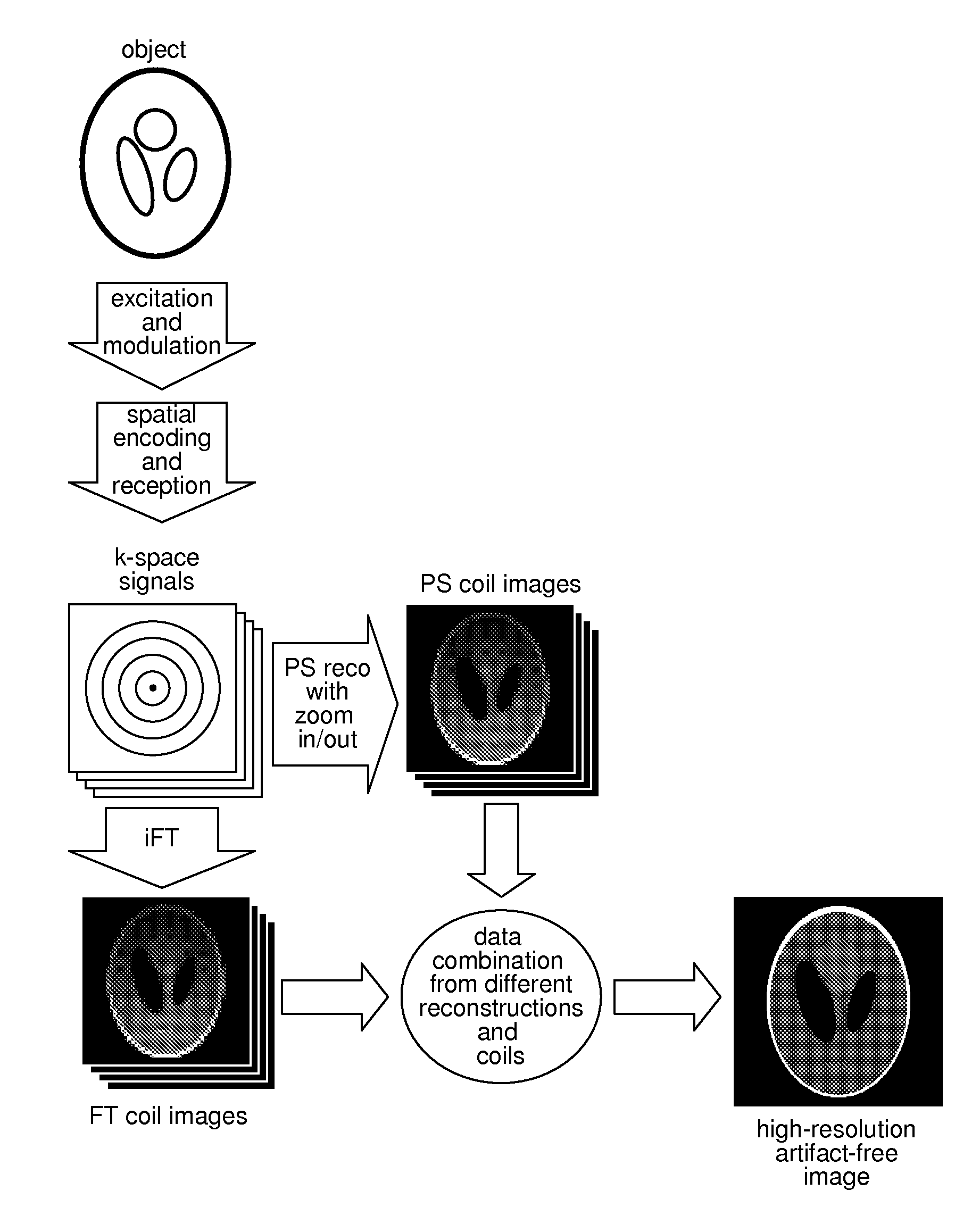
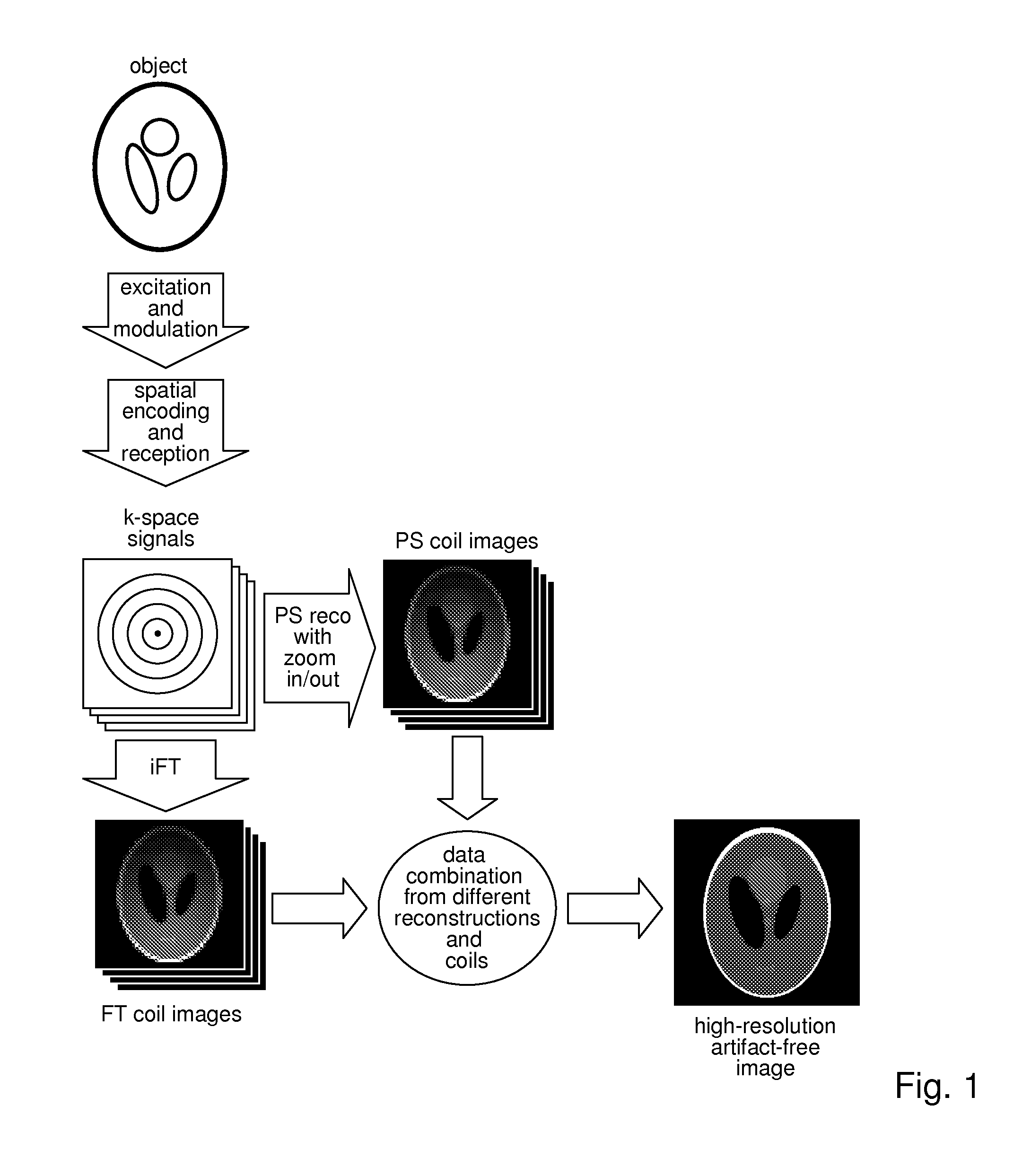
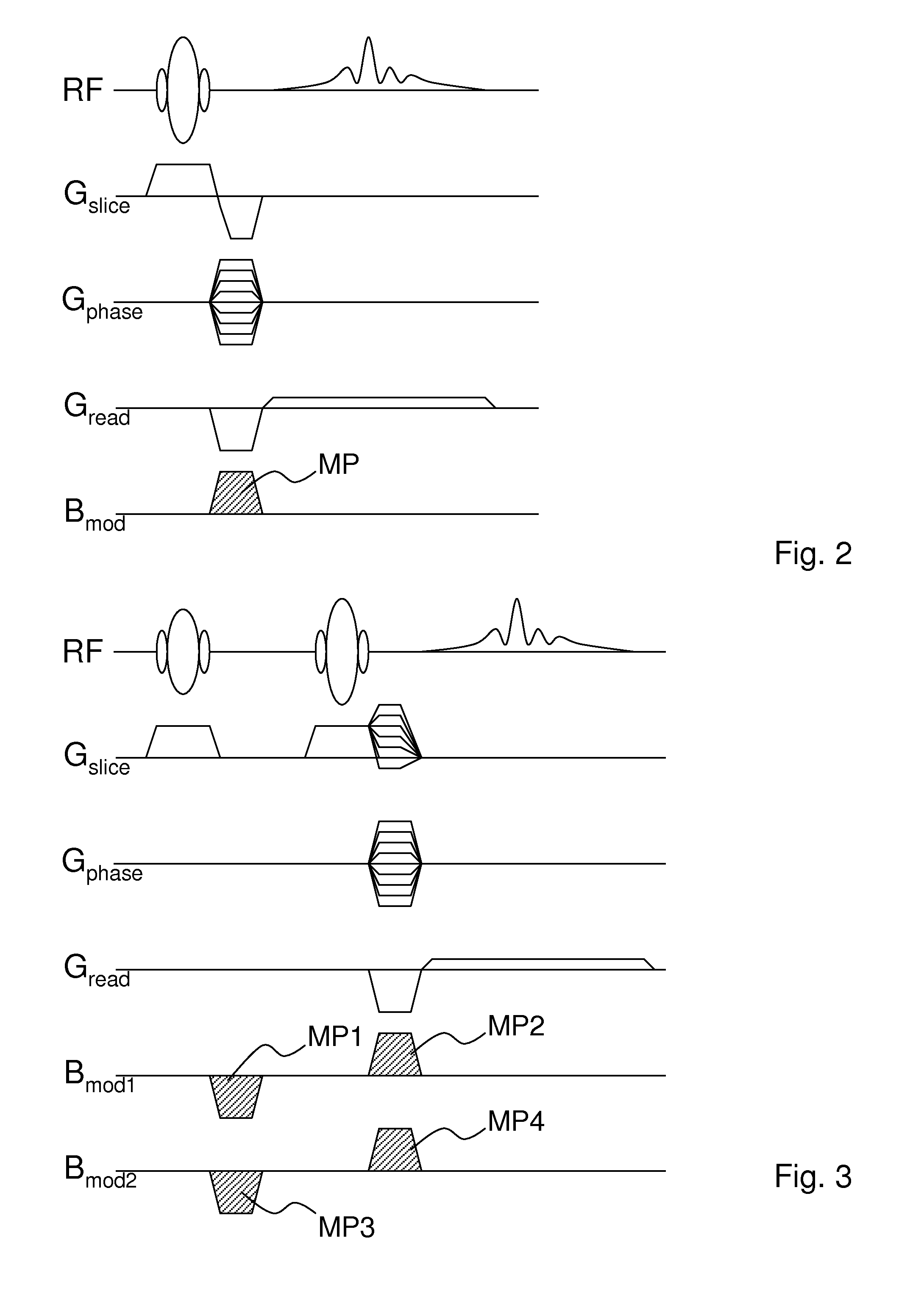
[0046]The present invention achieves an increased efficiency and thus time saving in spatial encoding of MR signals based on a combination of the non-linear spatial modulation of the phase of the signals with efficient signal reception using an RF receiver coil array. The scope of the present invention extends beyond the combined use of linear gradients for primary spatial encoding and quadratic phase modulation to achieve phase scrambling; indeed non-linear magnetic fields, as in PatLoc approach [12] or a combination of those fields with linear gradients may be used for primary spatial encoding in combination with a phase modulation function having a significantly non-linear representation in the distorted coordinate space defined by the primary encoding fields. E.g. phase modulation of the third or fourth order may be used in combination with a quadrupolar encoding fields. Additionally, more than a single phase modulation function can be applied to the different steps of the prima...


PUM


Abstract

A method for accelerating data acquisition in MRI with N-dimensional spatial encoding has a first method step in which a transverse magnetization within an imaged object volume is prepared having a non-linear phase distribution. Primary spatial encoding is thereby effected through application of switched magnetic fields. Two or more RF receivers are used to simultaneously record MR signals originating from the imaged object volume, wherein, for each RF receiver, an N-dimensional data matrix is recorded which is undersampled by a factor Ri per selected k-space direction. Data points belonging to a k-space matrix which were not recoded by a selected acquisition schema are reconstructed using a parallel imaging method, wherein reference information concerning receiver coil sensitivities is extracted from a phase-scrambled reconstruction of the undersampled data matrix. The method generates a high-resolution image free of artifacts in a time-efficient manner by improving data sampling efficiency and thereby reducing overall data acquisition time.

Description

BACKGROUND OF THE INVENTION[0001]The present invention relates to an MRI method and an MRI apparatus to implement the method which generates images using MR signals detected by an array of receiver coils. More specifically, the present invention relates to an MRI method and an MRI apparatus to generate a high-resolution image, free of artifacts, in a time-efficient manner. The present invention describes a method for accelerating data acquisition in MRI with N-dimensional spatial encoding.Nyquist Condition for MRI[0002]Conversion of analog spin induction signals recorded by the received coils to a set of discrete values is termed sampling. For time domain signal a sampling theorem exists, which requires the sampling frequency to exceed the maximum frequency observed in the spectrum of the recorded signal by a factor of two [2]. This is known as Shannon or Nyquist condition. For traditional MRI using linear magnetic field gradients, the time domain variable is replaced with a paramet...

Claims


Application Information

Patent Timeline
Patent Type & Authority Applications(United States)
IPC IPC(8): G01R33/44
CPCG01R33/5611G01R33/4836
Inventor ZAITSEV, MAXIMHENNIG, JUERGEN
Owner UNIVERSITATSKLINIKUM FREIBURG
Why Eureka
Try Eureka