Rotor assembly with cooling air deflectors and method

Active Publication Date: 2006-06-08
PRATT & WHITNEY CANADA CORP
View PDF14 Cites 50 Cited by
  • Summary
  • Abstract
  • Description
  • Claims
  • Application Information

AI Technical Summary

Benefits of technology

[0004] This present invention is generally aimed at reducing

Problems solved by technology

While systems are conventionally provided in gas turbine engines to induce a rotation of the cooling air before entering the manifolds, there is always a relatively large difference in the velocity of the air in front of the entrance of the manifolds and that of the periphery of the rotor disk where these manifolds are located.
Air entering in

Method used


Image

  • Rotor assembly with cooling air deflectors and method
  • Rotor assembly with cooling air deflectors and method
  • Rotor assembly with cooling air deflectors and method

Examples


Embodiment Construction

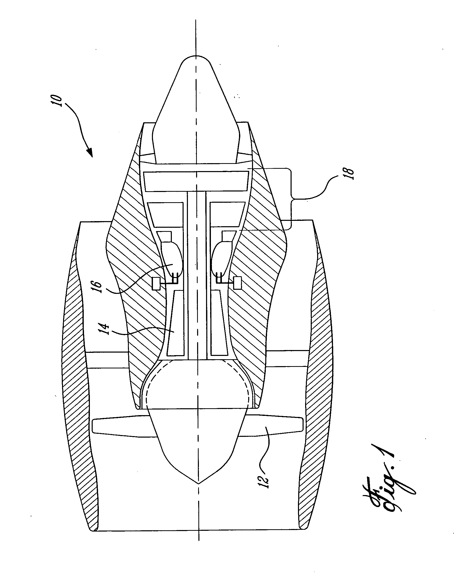
[0018]FIG. 1 illustrates an example of a gas turbine engine 10 of a type preferably provided for use in subsonic flight, generally comprising in serial flow communication a fan 12 through which ambient air is propelled, a multistage compressor section 14 for pressurizing the air, a combustor 16 in which the compressed air is mixed with fuel and ignited for generating an annular stream of hot combustion gases, and a turbine section 18 for extracting energy from the combustion gases. This figure illustrates an example of the environment in which the present invention can be used.

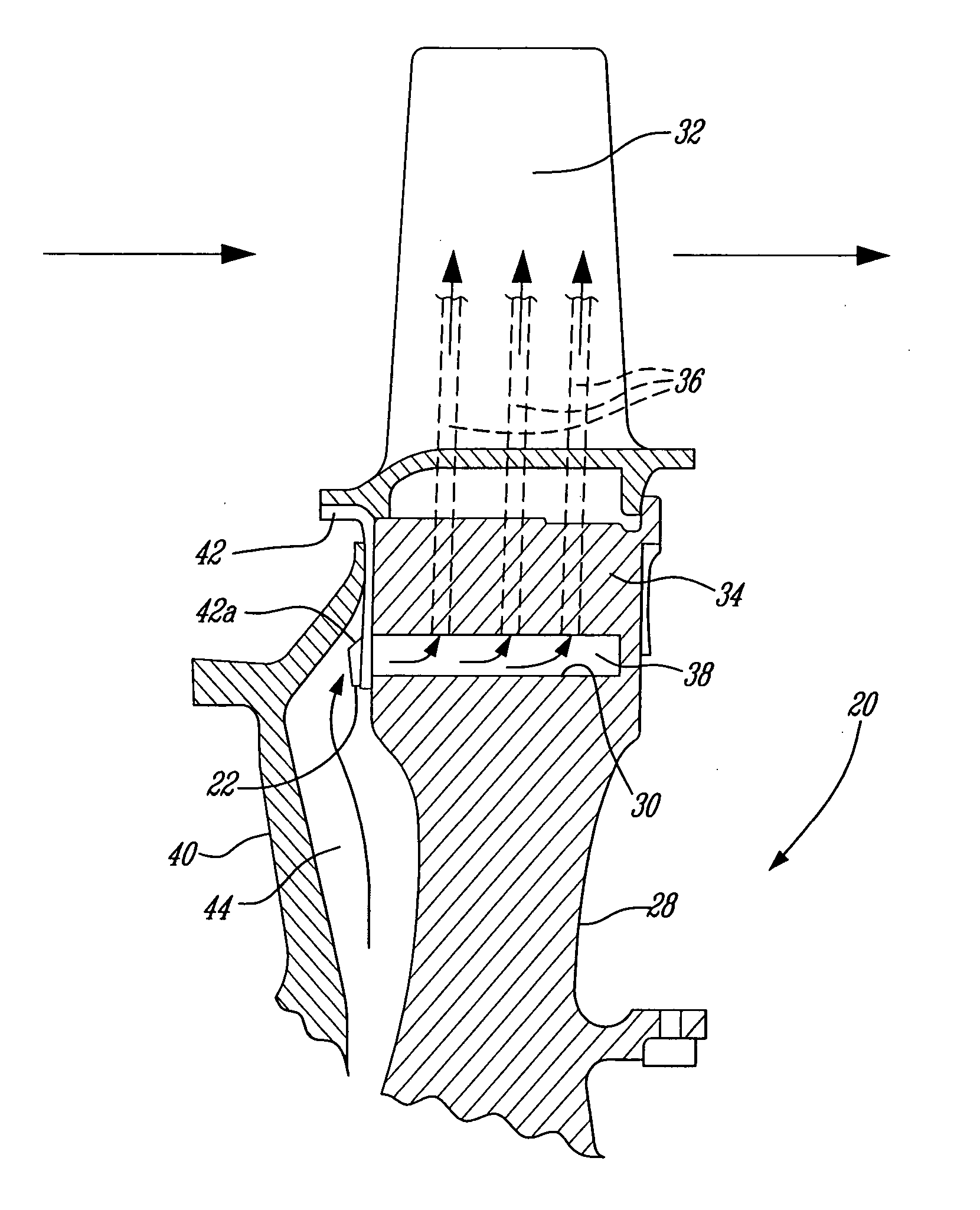
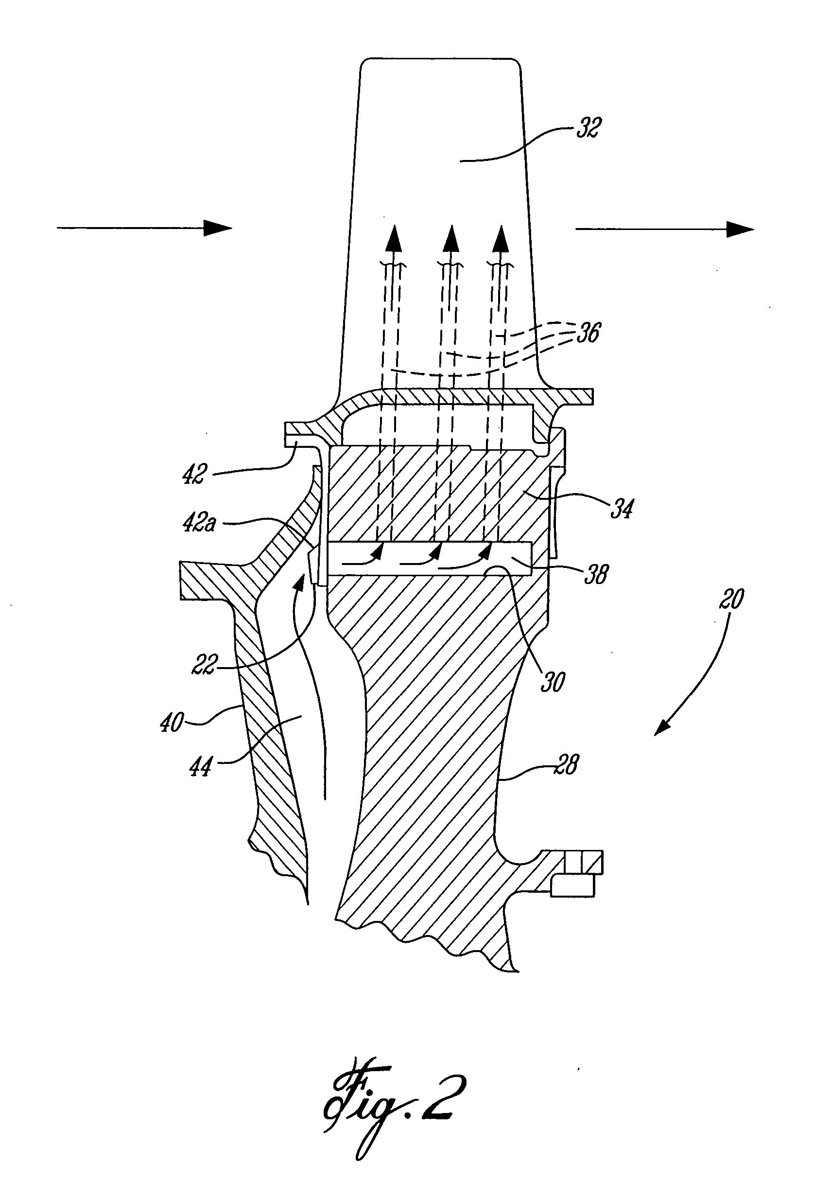
[0019]FIG. 2 illustrates an example of a rotor assembly 20 in which is provided air deflectors 22 in accordance with the present invention. Although FIG. 2 shows the rotor assembly 20 being provided in the turbine section 18 of a conventional gas turbine engine 10, it will be understood that the invention is equally applicable to a rotor assembly 20 used in the compressor section 14.

[0020] The rotor assembly...


PUM


Abstract

A rotor assembly for a gas turbine engine, the rotor assembly comprises a plurality of cooling air deflectors mounted on the rotor assembly to redirect air to a manifold at a bottom side of a corresponding blade retention slot on the periphery of the rotor disk.

Description

TECHNICAL FIELD [0001] The invention relates generally to gas turbine engines having internally-cooled blades receiving cooling air from a pressurized air supply system. BACKGROUND OF THE ART [0002] The design of pressurized cooling air supply systems in gas turbine engines is the subject of continuous improvements, including improvements to minimize pressure losses. One location where pressure losses can occur is at the entrance of the internal cooling passages of blades between the blade retention slots and the rotor disc, referred to hereafter as a manifold. [0003] In use, cooling air must enter the manifolds while they rotate with the rotor disk at very high speeds. Moreover, the inlet of the manifolds have a very high tangential velocity since they are located relatively far from the rotation axis. While systems are conventionally provided in gas turbine engines to induce a rotation of the cooling air before entering the manifolds, there is always a relatively large difference ...

Claims


Application Information

Patent Timeline
IPC IPC(8): F03B11/00
CPCF01D5/082F01D11/005F05D2250/292F05D2260/221F05D2250/51
Inventor DJERIDANE, TOUFIKPAPPLE, MICHAEL LESLIE CLYDESREEKANTH, SRIJUNEAU, ALANNADEAU, DOMINIQUE MICHEL
Owner PRATT & WHITNEY CANADA CORP
Why Eureka
Try Eureka