Honeycomb structural body

a technology of honeycomb and structural body, applied in the field of honeycomb structural body, can solve the problems of increasing pressure loss, affecting the performance of the engine, and affecting the quality of the engine, so as to reduce the load on the engine, and effectively utilize the capacity of large-capacity through holes

Inactive Publication Date: 2006-02-16
IBIDEN CO LTD
View PDF59 Cites 50 Cited by
  • Summary
  • Abstract
  • Description
  • Claims
  • Application Information

AI Technical Summary

Benefits of technology

[0030] The honeycomb structural body of the present invention makes it possible to suppress an increase in pressure loss upon collecting particulates. Moreover, the honeycomb structural body of the present invention also makes it possible to maintain the pressure loss caused by ash deposition at a low level for a long time even after regenerating processes, and consequently to effectively utilize the capacity of the large-capacity through holes; thus, it becomes possible to reduce a load imposed on the engine, and to provide a honeycomb structural body having a long service life. Thus, it becomes possible to cut maintenance costs required for back washing and the like.
[0036] a surface roughness Ry of the wall face of said through holes being set in a range from 10 to 100 μm.
[0037] The honeycomb structural body of the present invention is made of a columnar porous ceramic block in which a large number of through holes are placed in parallel with one another in the length direction with a wall portion interposed therebetween, however, the porous ceramic block may be constituted by combining a plurality of columnar porous ceramic members, each having a plurality of through holes that are placed in parallel with one another in the length direction with partition wall interposed therebetween, with one another through sealing material layers (hereinafter, also referred to as an aggregated honeycomb structural body), or may be formed by ceramic members that are integrally sintered as one unit as a whole (hereinafter, also referred to as an integral honeycomb structural body).
[0038] Moreover, the honeycomb structural body may contain the porous ceramic block, with a sealing material layer being formed on the circumference thereof.
[0039] In the case of the aggregated honeycomb structural body, the wall portion is constituted by a partition wall that separates through holes of porous ceramic members, an outer wall of the porous ceramic member and a sealing material layer that serves as a bonding agent layer between the porous ceramic members, and in the case of the integral honeycomb structural body, the wall portion is formed by a partition wall of one kind.
[0040] Moreover, the large number of through holes formed in the honeycomb structural body may comprise: a group of large-capacity through holes, each of which is sealed at one end of the honeycomb structural body such that the total sum of the areas on a cross section perpendicular to the length direction is made relatively great, and a group of small-capacity through holes each of which is sealed at the other end of the honeycomb structural body such that the total sum of the areas on the above-mentioned cross section is made relatively small.

Problems solved by technology

In recent years, particulates such as soot contained in exhaust gases discharged from internal combustion engines of vehicles such as buses, trucks and the like and construction machines have raised serious problems as those particulates are harmful to the environment and the human body.
However, in the above-mentioned conventional honeycomb filters, ashes that remain as dregs after particulates have been burnt are accumulated on the wall face of the through holes as they are without being moved.
For this reason, the problems with the above-mentioned structures are that pores, formed in the partition wall, are closed and that the ashes tend to form bridges to cause clogging in the through holes, resulting in an abrupt rise in the pressure loss.
Consequently, the burning speed of particulates becomes too fast, with the result that ashes are deposited on the wall faces of the through holes, as they are, without being moved, and the ashes tend to form bridges to cause clogging in the through holes, resulting in an abrupt rise in the pressure loss.

Method used


Image

  • Honeycomb structural body
  • Honeycomb structural body
  • Honeycomb structural body

Examples


example 1

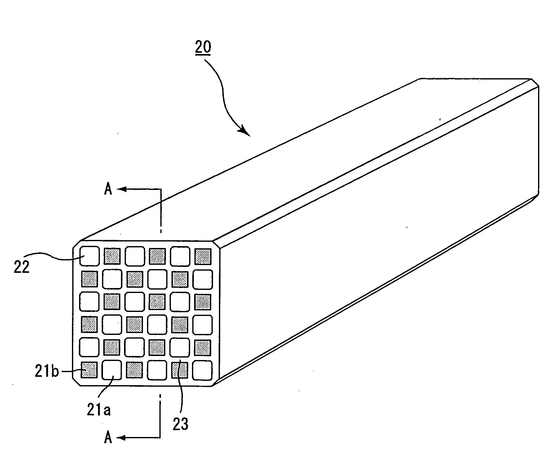
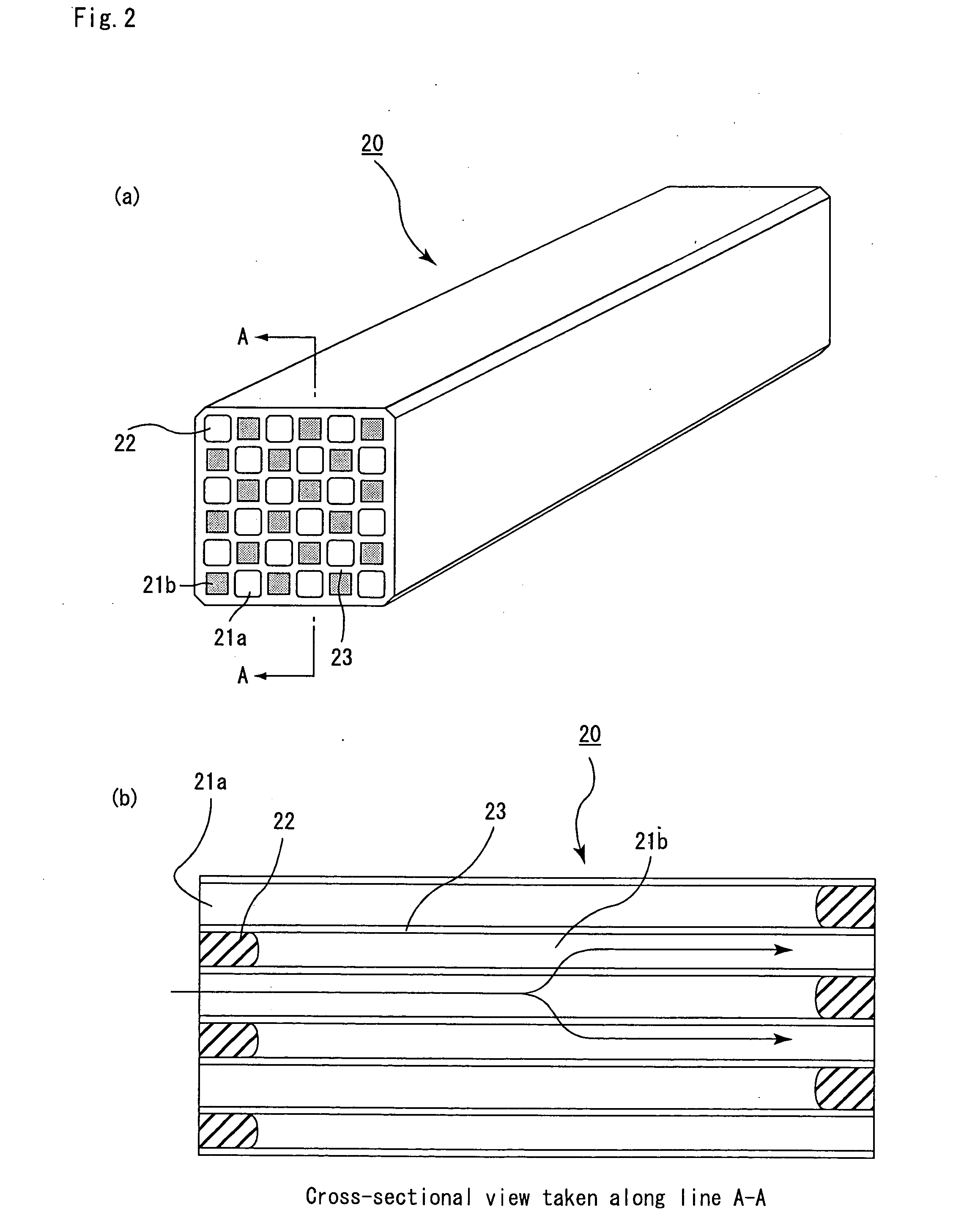
[0137] (1) Powder of α-type silicon carbide having an average particle size of 11 μm (60% by weight) and powder of β-type silicon carbide having an average particle size of 0.5 μm (40% by weight) were wet-mixed, and to 100 parts by weight of the resulting mixture were added and kneaded 5 parts by weight of an organic binder (methyl cellulose) and 10 parts by weight of water to obtain a mixed composition. Next, after a slight amount of a plasticizer and a lubricant have been added and kneaded therein, the resulting mixture was extrusion-molded by using a metal mold having a surface roughness Ra of 10 μm at the portions corresponding to the through holes so that a raw molded product, which had almost the same cross-sectional shape as each of the cross-sectional shapes shown in FIGS. 4(a) to 4(d), was manufactured with an aperture ration of 2.54.

[0138] Next, the above-mentioned raw molded product was dried by using a micro-wave drier to form a ceramics dried body, and after predetermi...

examples 2 to 6 and 11 to 13

)

[0145] The same processes as Example 1 were carried out except that in the process (1), the cross-sectional shapes of the large-capacity through holes and the small-capacity through holes were formed into shapes as shown in Table 1, with the wall thickness being set to a value shown in Table 1, so that a porous ceramic member was manufactured, and a honeycomb structural body was then produced. The wall thickness, the surface roughness Ry of through-hole wall faces, the density of the through holes and the porosity of the resulting honeycomb structural body are shown in Table 1.

example 7

[0146] The same processes as Example 1 were carried out except that in the process (1), the cross-sectional shapes of the large-capacity through holes and the small-capacity through holes were formed into shapes as shown in Table 1, with the sintering conditions changed to 2000° C. and 3 hours, so that a porous ceramic member was manufactured, and a honeycomb structural body was then produced.

[0147] The wall thickness, the surface roughness Ry of through-hole wall faces, the density of the through holes and the porosity of the resulting honeycomb structural body are shown in Table 1.


PUM

PropertyMeasurementUnit
surface roughness Ryaaaaaaaaaa
surface roughnessaaaaaaaaaa
heightaaaaaaaaaa

Abstract

An object of the present invention is to provide a honeycomb structural body with a long service life, which can reduce a pressure loss to a low level upon collecting particulates and maintain the pressure loss at the low level for a long time even after regenerating processes. The honeycomb structural body includes a columnar porous ceramic block in which a large number of through holes are placed in parallel with one another in the length direction with a wall portion interposed therebetween. Herein, the large number of through holes are constituted by a group of large-capacity through holes, each of which is sealed at one end of the honeycomb structural body so that the total sum of the areas on a cross section perpendicular to the length direction is made relatively great, and a group of small-capacity through holes, each of which is sealed at the other end of the honeycomb structural body so that the total sum of the areas on the cross section is made relatively small, and a surface roughness Ry of the wall face of the through hole is set in a range from 10 to 100 μm.

Description

TECHNICAL FIELD [0001] This application claims benefit of priority to Japanese Patent Application No. 2003-161261, filed on Jun. 5, 2003, the contents of which are incorporated by reference herein. The present invention relates to a honeycomb structural body that is used as a filter for removing particulates and the like contained in exhaust gases discharged from an internal combustion engine such as a diesel engine or the like. BACKGROUND ART [0002] In recent years, particulates such as soot contained in exhaust gases discharged from internal combustion engines of vehicles such as buses, trucks and the like and construction machines have raised serious problems as those particulates are harmful to the environment and the human body. [0003] There have been proposed various ceramic filters which allow exhaust gases to pass through porous ceramics and collect particulates in the exhaust gases, thereby purifying the exhaust gases. [0004] Conventionally, with respect to the honeycomb fi...

Claims


Application Information

Patent Timeline
Patent Type & Authority Applications(United States)
IPC IPC(8): B01D39/20B01D46/00B01D46/24B01J35/04F01N3/022F01N3/28
CPCB01D46/0063Y10T428/24149B01D46/2429B01D46/2451B01D46/2459B01D46/247B01D46/2474B01D2046/2433B01D2046/2477B01D2046/2481B01D2046/2485B01D2046/2492B01D2046/2496F01N3/0222F01N3/2828F01N2330/06F01N2330/34F01N2330/48F01N2350/02Y02T10/20B01D46/2425Y02T10/12B01D46/2494B01D46/249B01D46/2498B01D46/2486B01D46/84B01D46/2478B01D46/2484B01D46/2476F01N3/022F01N3/02
Inventor KOMORI, TERUOOHNO, KAZUSHIGEHONG, SUNGTAEOSHIMI, YUKIO
Owner IBIDEN CO LTD
Why Eureka
Try Eureka