In-line strainer

Inactive Publication Date: 2010-05-13
KMC
View PDF11 Cites 14 Cited by
  • Summary
  • Abstract
  • Description
  • Claims
  • Application Information

AI Technical Summary

Benefits of technology

[0017]According to the present invention, therefore, the flow passageway of the in-line strainer is formed in the same direction as the pipeline, such that the flow passageway resistance of the fluid flowing along the pipeline and the generation of vortexes in the fluid are all reduced, thereby ensuring the gentle and stable fluid flow and the reduction of the loss of pressure.
[0018]According to the present invention, fur

Problems solved by technology

By the way, foreign matters like dust, scales, and so on may enter the interior of the pipeline from the outside to cause the formation of impurities in the fluid flowing along the pipeline, and in this case, the valve and the fluid pump conveying the fluid are damaged to reduce their life span.
Moreover, the valve and the pipe are closed, such that they do not work anymore.
Since the flow passageway is curved, additionally, the body 1 is worn out by the friction against the fluid, and the stress in the pipeline

Method used


Image

  • In-line strainer
  • In-line strainer
  • In-line strainer

Examples


first embodiment

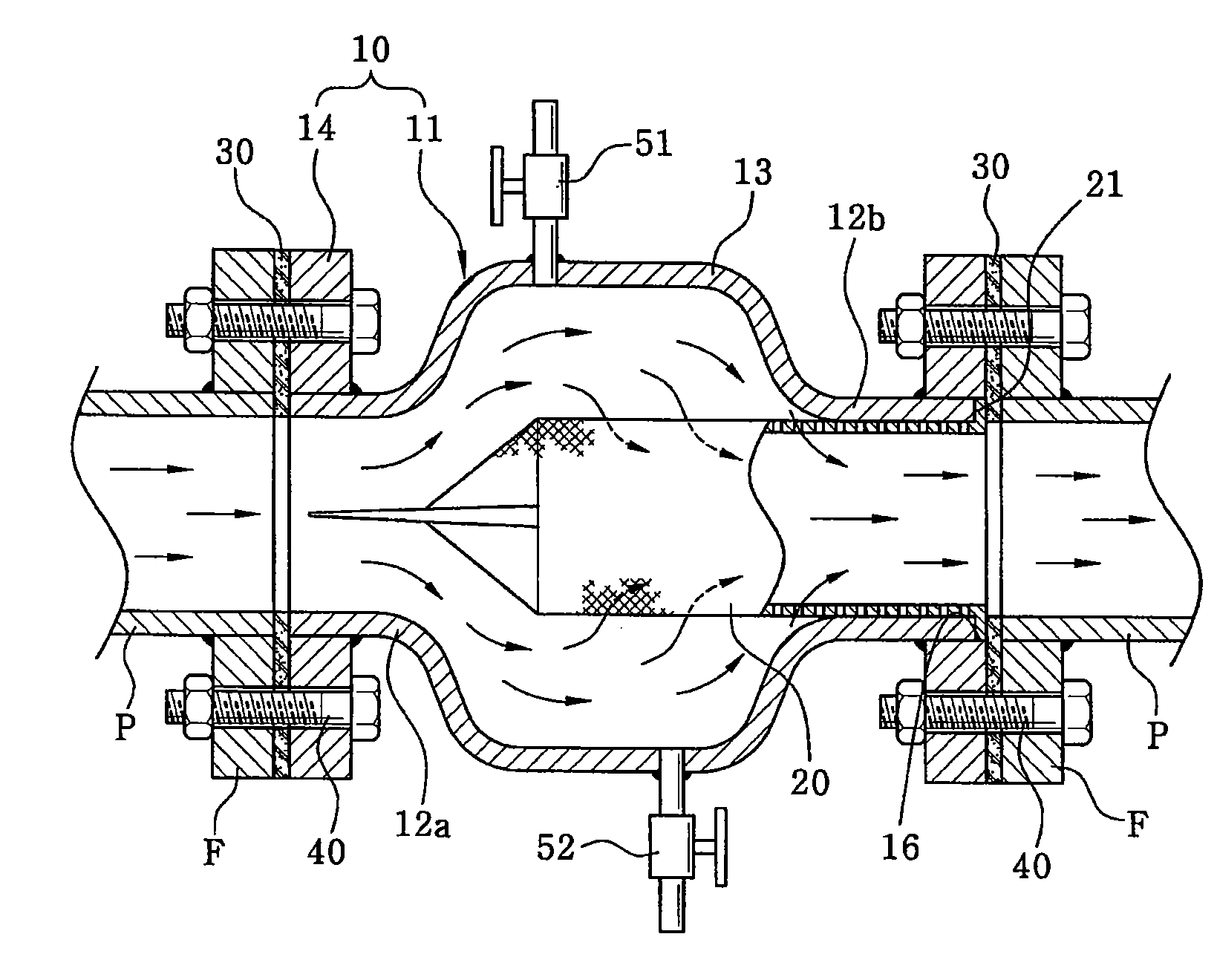
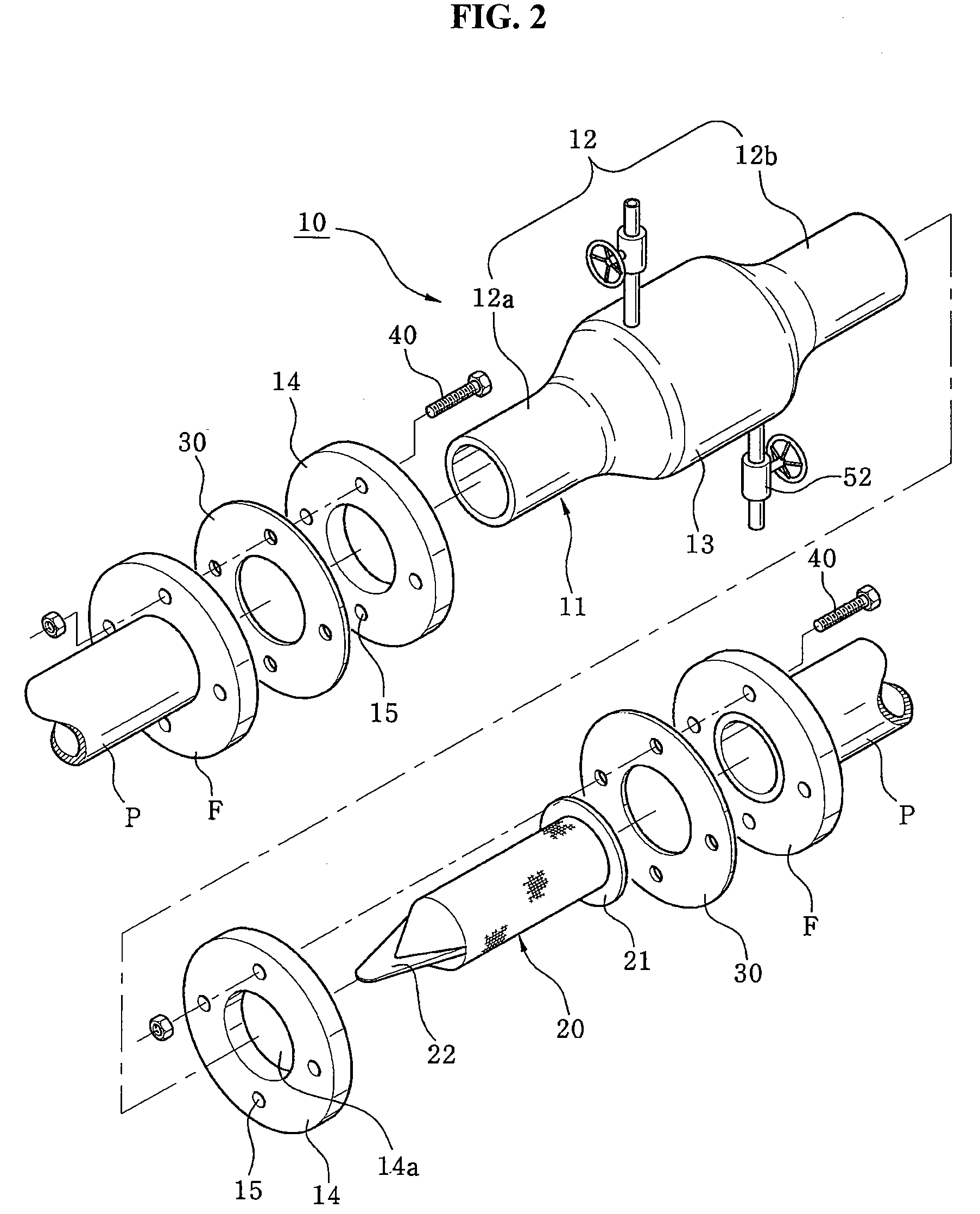
[0028]As shown in FIGS. 2 and 3, an in-line strainer according to the present invention includes: a body 10 formed of a linear pipe having an enlarged part 13 formed increased in diameter in the middle portion thereof and connected coaxially to a pipeline P; and a mesh screen 20 adapted to be inserted into the enlarged part 13 of the body 10 and disposed concentrically in the pipeline P, having a predetermined space from the body 10, so as to filter foreign matters W contained in the fluid flowing along the pipeline P.

[0029]The body 10 has a fastening flange 14 mounted at the both ends thereof in such a manner as to be connected coaxially to the pipeline P by fastening a flange F of the pipeline P and a gasket 30 to the fastening flange 14 by means of bolts 40, the fastening flange 14 having a plurality of fastening holes 15 formed at predetermined intervals thereon.

[0030]The body 10 may be formed of a single body by means of molding, but preferably, the body 10 is formed of a metal...

second embodiment

[0048]According to the present invention, if the strainer is mounted on the pipeline P vertically formed, the foreign matters W accumulated on the bottom of the enlarged part 13 of the body 10 are easily removed, without any separation of the strainer from the pipeline P.

[0049]As mentioned above, the in-line strainer according to the present invention has the flow passageway formed in the same direction as the pipeline in which the strainer is disposed, thereby substantially reducing the flow passageway resistance of the fluid flowing along the pipeline and the generation of the vortexes in the pipeline, which ensures the gently and stable conveyance of the fluid and the reduction of the loss of pressure.

[0050]In addition, the in-line strainer of this invention reduces the friction and stress caused by the flow friction against the fluid flowing along the pipeline, thereby increasing the durability thereof, and has a relatively small, simple and light body, thereby making it easy to...


PUM

PropertyMeasurementUnit
Diameteraaaaaaaaaa
Shapeaaaaaaaaaa

Abstract

The present invention relates to an in-line strainer including: a body formed of a linear pipe having an enlarged part formed increased in diameter in the middle portion thereof, and a fastening flange mounted at the both ends thereof in such a manner as to be connected coaxially to a pipeline by means of a gasket; and a mesh screen having a generally conical shape at the front end portion thereof and a generally cylindrical shape at the back end portion thereof in such a manner as to be coupled to the body, the mesh screen being inserted from the outlet port of the body and being disposed concentrically into the enlarged part of the body in such a manner as to place the front end portion thereof into the enlarged part of the body, having a predetermined space from the inlet port of the body.

Description

BACKGROUND OF THE INVENTION[0001]1. Field of the Invention[0002]The present invention relates to a strainer that is disposed in a variety of pipelines for conveying fluids therealong so as to filter foreign matters contained in the fluids, and more particularly, to an in-line strainer that has a flow passageway formed in the same direction as a pipeline in which the strainer is disposed, thereby substantially reducing the generation of vortexes, the frictional resistance, and the loss of pressure caused by the curving of the flow passageway.[0003]2. Background of the Related Art[0004]Generally, a pipeline formed of pipes is employed to convey a variety of fluids like oil, water, gas and steam, and further, a valve is mounted at a predetermined position on the pipeline, so as to conduct or stop the supply of the fluid, and alternatively, so as to appropriately adjust the flow rate of the fluid.[0005]By the way, foreign matters like dust, scales, and so on may enter the interior of th...

Claims


Application Information

Patent Timeline
IPC IPC(8): B01D35/02
CPCB01D29/114B01D35/02B01D2201/02B01D29/96B01D35/16
Inventor JUNG, CHANG-MOO
Owner KMC
Why Eureka
Try Eureka