Air conditioning system

Inactive Publication Date: 2011-04-26
DAIKIN IND LTD
View PDF8 Cites 14 Cited by
  • Summary
  • Abstract
  • Description
  • Claims
  • Application Information

AI Technical Summary

Benefits of technology

[0032]In the third solution, the air conditioning system is configured to allow the air to concurrently flow in parallel flows through the utilization side heat exchanger (55) and the adsorption heat exchanger (56, 57) and then supply the flows of air to the room space. In this case, the pressure loss produced with air flowing is reduced as compared with when the air sequentially flows through, for example, the utilization side heat exchanger (55) and the adsorption heat exchanger (56, 57). This provides reduced power for an air blower for blowing the air and in turn a downsized air blower.
[0033]Further, since the utilization side heat exchanger (55) and the adsorption heat exchanger (56, 57) concurrently can cope with the corresponding flows of air, the amount of air flowing through the utilization side heat exchanger (55) and the amount of air flowing through the adsorption heat exchanger (56, 57), for example, can be separately controlled and the air temperature control and air humidity control can be carried out individually. This increases the flexibility of air conditioning using the air conditioning system and thereby enhances the comfortableness of the room space.
[0034]In the fourth solution, during the humidification heating operation, the air conditioning system is configured to cool, in the heat-source side heat exchanger (54), the air the moisture in which has been adsorbed by the adsorption heat exchanger (56, 57) and then discharge the air to the outdoor space. In this case, since the air being cooled by the heat-source side heat exchanger (54) has been dehumidified by the adsorption heat exchanger (56, 57), this reduces the amount of condensate produced near the heat-source side heat exchanger (54) with the air cooling. Therefore, drain water can be restrained from being produced in the heat-source side heat exchanger (54) and a system for drain can be downsized. Further, if the heat-source side heat exchanger (54) is disposed in the outdoor space, it can be prevented that condensate freezes on the surface of the heat-source side heat exchanger (54).
[0

Problems solved by technology

This provides a large difference between high and low pressures in the refrigeration cycle and raises the input to the compressor, which leads to a problem that only a small

Method used


Image

  • Air conditioning system
  • Air conditioning system
  • Air conditioning system

Examples


embodiment 1

of the Invention

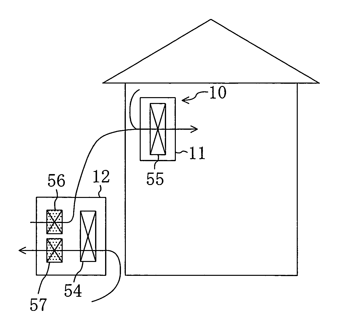
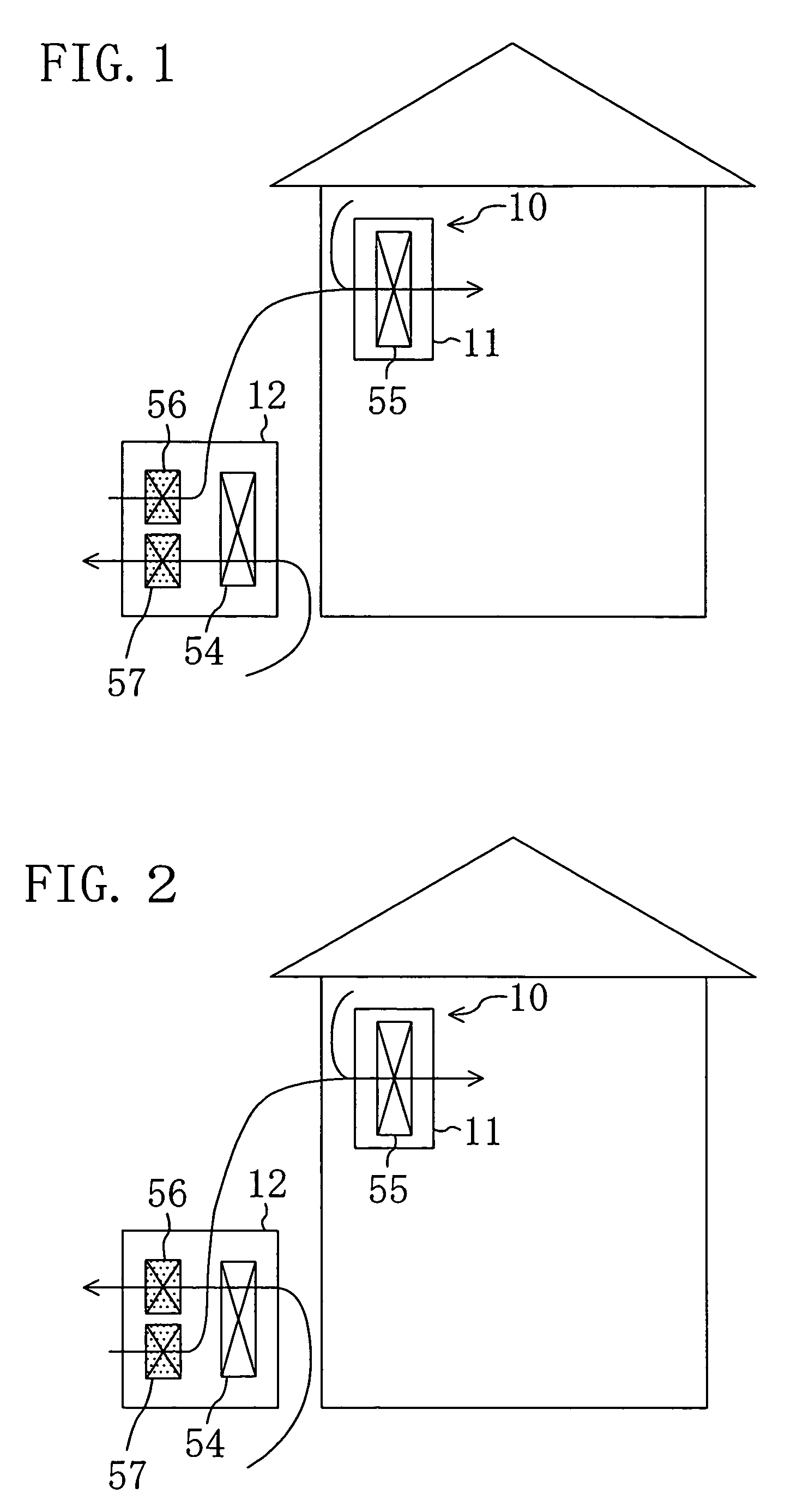
[0058]Embodiment 1 of the present invention is described. An air conditioning system (10) of the present embodiment runs a vapor compression refrigeration cycle by circulating refrigerant through a refrigerant circuit (40) to cope with both of sensible heat load and latent heat load in a room space. The refrigerant circuit (40) of the air conditioning system (10) is provided with an outdoor heat exchanger (54) as a heat-source side heat exchanger, an indoor heat exchanger (55) as a utilization side heat exchanger and two adsorption heat exchangers (first and second adsorption heat exchangers) (56, 57).

[0059]As shown in FIGS. 1 and 2, the air conditioning system (10) is configured as a so-called separate type and includes an indoor unit (11) and an outdoor unit (12). The indoor unit (11) includes the indoor heat exchanger (55) and is disposed in the room space. On the other hand, the outdoor unit (12) includes the outdoor heat exchanger (54), the first adsorption heat...

embodiment 2

of the Invention

[0104]Next, Embodiment 2 of the present invention is described. As shown in FIGS. 7 and 8, the air conditioning system (10) of Embodiment 2 is configured, like Embodiment 1, as a so-called separate type and includes an indoor unit (11) and an outdoor unit (12). A refrigerant circuit (40) of the air conditioning system (10) is provided with an outdoor heat exchanger (54), an indoor heat exchanger (55) and first and second adsorption heat exchangers (56, 57).

[0105]The indoor unit (11) includes an indoor heat exchanger (55), the first adsorption heat exchanger (56) and the second adsorption heat exchanger (57) and is disposed in the room space. On the other hand, the outdoor unit (12) includes the outdoor heat exchanger (54) and is disposed in the outdoor space.

[0106]As shown in FIGS. 7 and 8, the air conditioning system (10) of Embodiment 2 is configured to allow the air to concurrently flow in parallel flows through the indoor heat exchanger (55) and the adsorption he...

embodiment 3

of the Invention

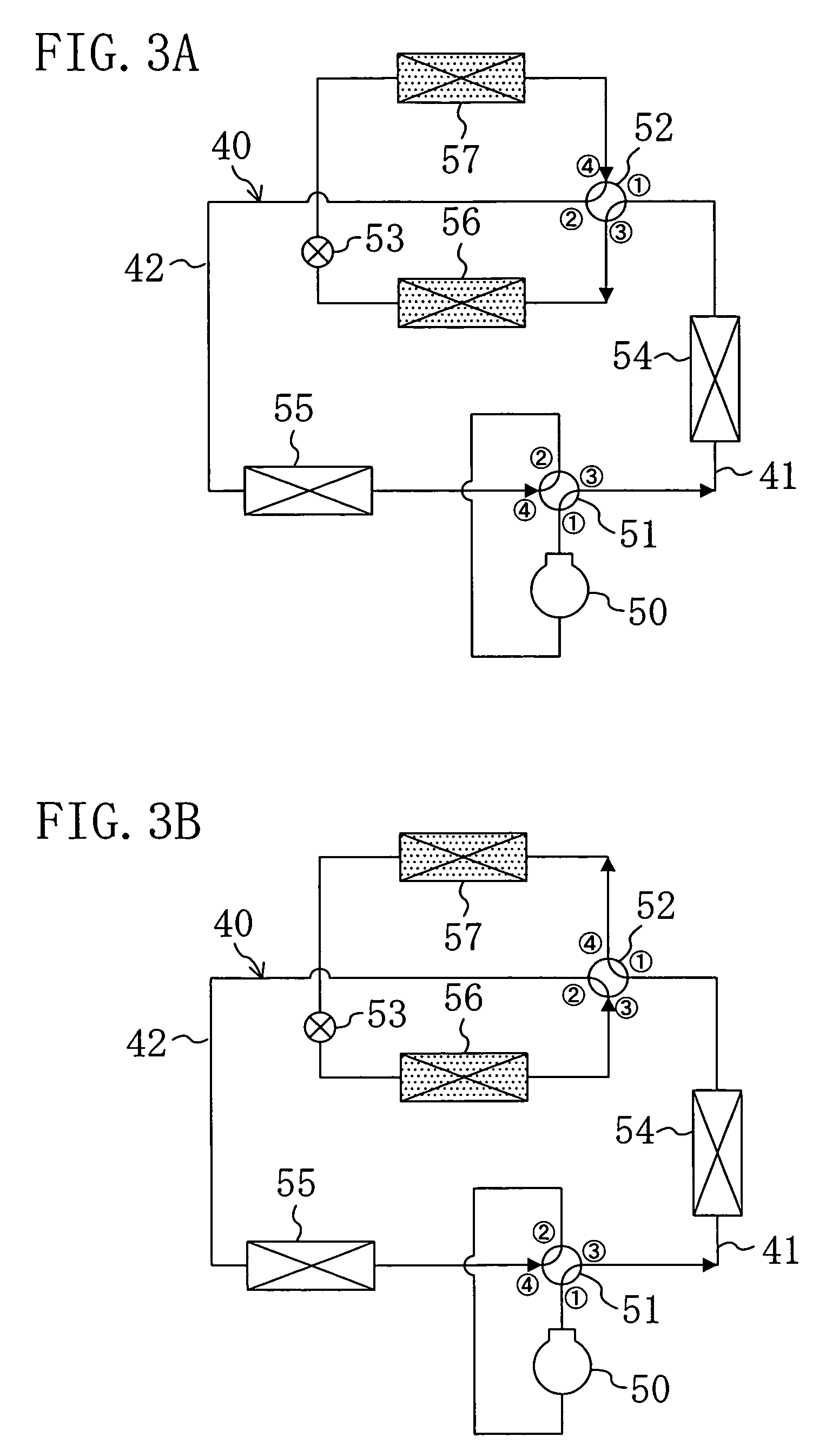
[0146]Next, an air conditioning system (10) of Embodiment 3 of the present invention is described with reference to several drawings. A refrigerant circuit (40) of the air conditioning system (10) is provided with an outdoor heat exchanger (54), an indoor heat exchanger (55) and first and second adsorption heat exchangers (56, 57). The rest of the configuration of the refrigerant circuit (40) is the same as in the above Embodiments 1 and 2 as shown in FIGS. 3 and 4.

[0147]As shown in FIGS. 11 and 12, the air conditioning system (10) is configured as a so-called separate type and includes an indoor unit (11) and an outdoor unit (12). The indoor unit (11) includes the indoor heat exchanger (55) and is disposed in a room space. The indoor unit (11) is configured as a so-called wall-mounted type, namely, is mounted on a wall surface of the room. On the other hand, the outdoor unit (12) includes the outdoor heat exchanger (54), the first adsorption heat exchanger (56) and ...


PUM


Abstract

A refrigerant circuit (40) is provided with an outdoor heat exchanger (54), an indoor heat exchanger (55) and two adsorption heat exchangers (56, 57). The indoor heat exchanger (55) is disposed in an indoor unit (11), while the outdoor heat exchanger (54) and the two adsorption heat exchangers (56, 57) are disposed in an outdoor unit (12). Moisture in outdoor air taken in the outdoor unit (12) is adsorbed by the adsorbent in the adsorption heat exchanger (56, 57) serving as an evaporator and the air is dehumidified. The dehumidified air is cooled by the indoor heat exchanger (55) serving as an evaporator and the air is supplied to the room space.

Description

TECHNICAL FIELD[0001]This invention relates to air conditioning systems for coping with sensible heat load and latent heat load in a room space.BACKGROUND ART[0002]An air conditioning system for providing cooling and dehumidification of a room space is known in the art as disclosed in Patent Document 1 (WO03 / 029728 pamphlet). The air conditioning system includes a refrigerant circuit provided with an indoor heat exchanger as a utilization side heat exchanger and an outdoor heat exchanger as a heat-source side heat exchanger and runs a refrigeration cycle by circulating refrigerant through the refrigerant circuit. Further, the air conditioning system dehumidifies the room space by setting the refrigerant evaporation temperature in the indoor heat exchanger below the dew point of the room air and condensing moisture in the room air.[0003]A dehumidifier is also known which includes heat exchangers each provided with an adsorbent on the surface thereof, as disclosed in Patent Document 2...

Claims


Application Information

Patent Timeline
IPC IPC(8): F25B27/00F24F1/02F24F3/14F24F3/153F24F11/02F25B5/04F25B6/04F25B13/00F25B29/00
CPCF24F1/0003F24F3/1429F24F6/00F24F3/1411B01D2253/106B01D2253/108B01D2259/4508F25B13/00F25B2313/02341F25B2313/02543F24F3/12F24F3/14
Inventor MATSUI, NOBUKIIKEGAMI, SHUJIYABU, TOMOHIRO
Owner DAIKIN IND LTD
Why Eureka
Try Eureka