Dust cup filter and dust collector provided with same

A filter and dust cup technology, used in vacuum cleaners, suction filters, cleaning equipment, etc., can solve the problems of small filtering area, complex structure design, insufficient suction, etc., to increase the air passage area, improve the filtering efficiency, and simplify the overall effect of structure

Active Publication Date: 2017-02-15
KINGCLEAN ELECTRIC
View PDF7 Cites 15 Cited by
  • Summary
  • Abstract
  • Description
  • Claims
  • Application Information

AI Technical Summary

Problems solved by technology

[0004] At present, the filter device in the prior art is a circular flat filter cotton with a small filter area, and the filter cotton is set inside the dust cup, and the dust cup cover needs to be opened before taking it, which is inconvenient to operate
[0005] In order to solve the problem of inconvenient access, a filter with a columnar structure is disclosed in the prior art. The filter is directly inserted into the dust cup and fixed, and the handle leaks out from the outside for easy access, but the opening of the filter is located at the top In the circumferential direction, after the dust and gas are separated, the dust needs to run upward first, then enter the filter through the radial direction of the filter, then run downward along the axial direction of the filter, and be discharged radially outward from the inside of the filter. During this process, the dust is adsorbed on the inner wall of the filter, and the gas is discharged
Since the dust gas needs to run from bottom to top and then radially enter the filter, and then radially exit the filter after being filtered from top to bottom, the path of the entire dust gas flow is long, the pressure loss is large, and the suction is insufficient. The device is a slender columnar structure. Compared with the cylindrical structure with the same area, its air outlet rate is lower. Moreover, multiple air inlets need to be opened on its top circumference, so its structural design is relatively complicated and the processing cost is relatively high. high

Method used


Image

  • Dust cup filter and dust collector provided with same
  • Dust cup filter and dust collector provided with same
  • Dust cup filter and dust collector provided with same

Examples


Embodiment Construction

[0030] As mentioned in the background technology section, the filter device in the prior art is a circular flat filter cotton with a small filter area, and the filter cotton is arranged inside the dust cup, and the dust cup cover needs to be opened before taking it, which is inconvenient to operate .

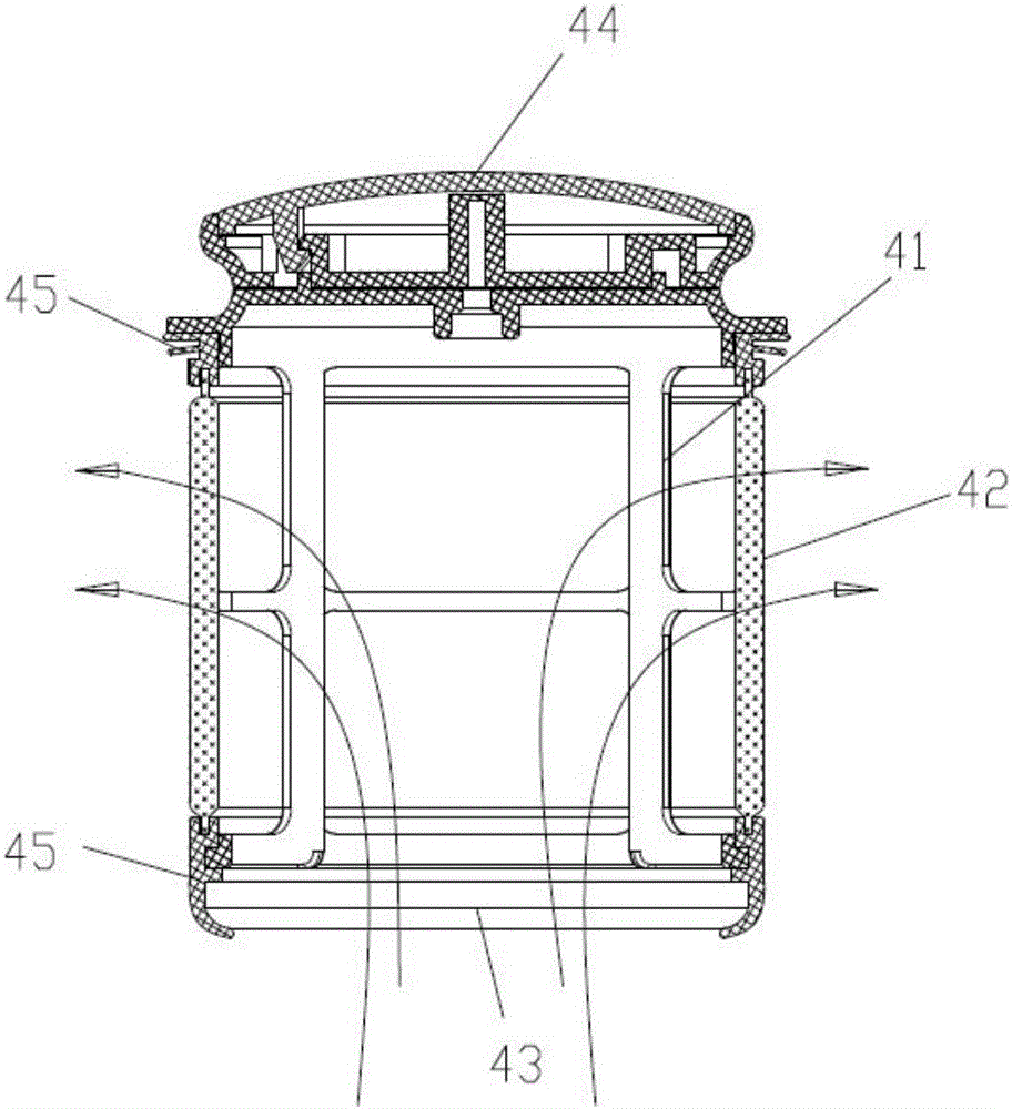
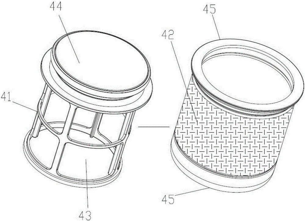
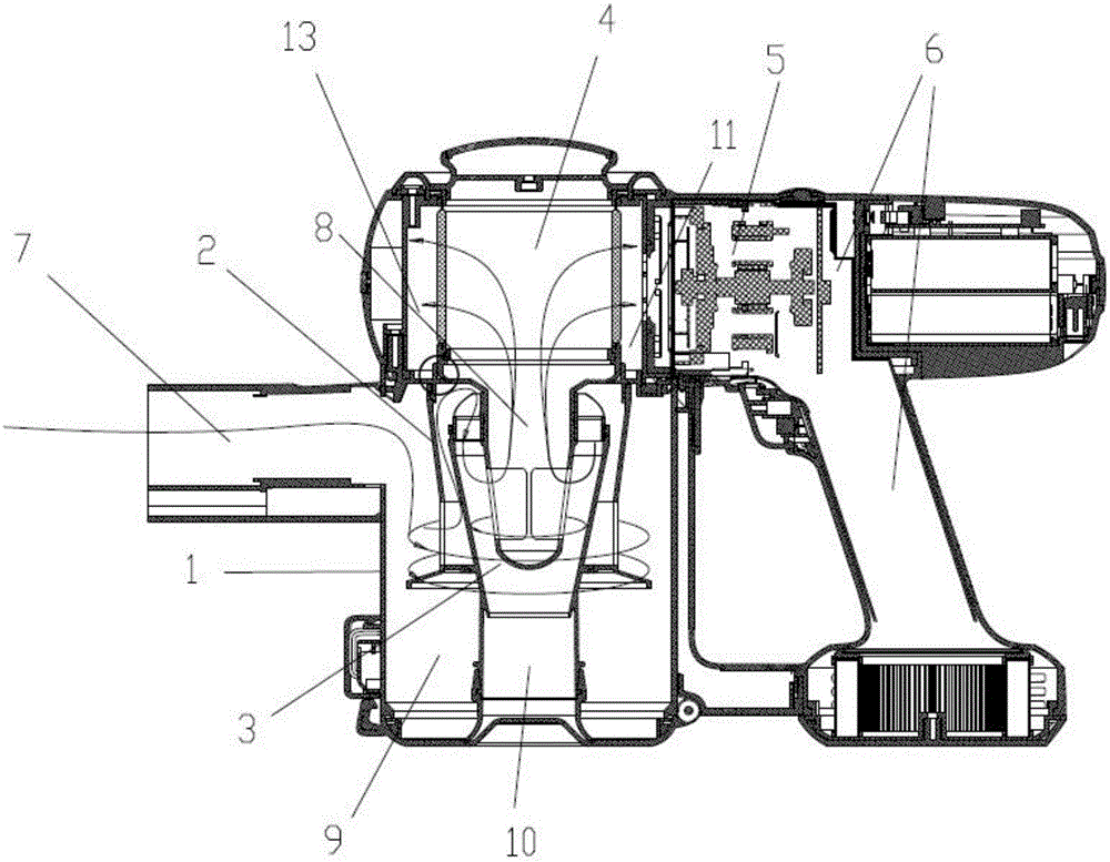
[0031] Aiming at the deficiencies in the prior art, the present invention provides a dust cup filter. By changing the air intake mode of the filter, the dust gas separated by the cyclone dust gas separation device directly enters the interior of the filter upward and axially, and is passed Radial discharge can effectively shorten the dust flow path; by changing the structure of the filter, the side of the cylindrical structure is used as the filter surface to more effectively increase the air passing area, reduce pressure loss, improve filtration efficiency, and simplify the overall structure ,cut costs.

[0032] The technical solutions of the present invention will be clearly ...


PUM


Abstract

The invention discloses a dust cup filter. A cyclone dust-gas separating device is arranged in a dust cup, the dust cup filter is arranged above the cyclone dust-gas separating device, dust and gas enter from a gas inlet of the dust cup, pass through the cyclone dust-gas separating device in the dust cup and then enters into the interior of the filter upwards, and gas is discharged along an air outlet air channel of the dust cup after filtration of the interior of the filter toward the exterior. The dust cup filter disclosed by the invention has the advantages that an air passing area is increased more effectively by changing the structural form of the filter, filtration efficiency is improved, the filter is detachably arranged at the top of the dust cup and can be cleaned after being taken upward directly, a dust cup cover does not need to be opened, and operation is easy.

Description

technical field [0001] The invention belongs to the technical field of structural design of a dust cup filter, and in particular relates to a dust cup filter and a vacuum cleaner provided with the filter. Background technique [0002] Vacuum cleaners, as a household electrical appliance, are widely used in indoor and outdoor cleaning. Existing vacuum cleaners can be classified into horizontal, vertical, and hand-held types according to their shapes. The hand-held vacuum cleaner is small in size and very convenient to carry and use. It is a household cleaning product between ordinary household vacuum cleaners and portable vacuum cleaners. It is suitable for cleaning small spaces and is mainly used for cleaning inside the car, for keyboards, electrical appliances Wait for a good cleaning effect. Hand-held vacuum cleaners usually have their own batteries as power, which is convenient for cleaning cars or outdoor items. As a result, more and more Chinese families have begun to ...

Claims


Application Information

Patent Timeline
Patent Type & Authority Applications(China)
IPC IPC(8): A47L5/24A47L9/12A47L9/16A47L9/32
CPCA47L5/24A47L9/12A47L9/1616A47L9/322
Inventor 倪祖根
Owner KINGCLEAN ELECTRIC
Why Eureka
Try Eureka