Turbine Having Compact Inflow Housing Thanks to Internal Control Valves

a technology of internal control valves and inflow housings, which is applied in the direction of pump installations, machines/engines, mechanical equipment, etc., can solve the problems of large space occupation of the inflow housing with the external valve compartment or the pipes, high construction costs, and significant energy losses, and achieves a compact construction. , the effect of reducing the flow loss caused by long lines

Inactive Publication Date: 2010-07-15
SIEMENS AG
View PDF8 Cites 9 Cited by
  • Summary
  • Abstract
  • Description
  • Claims
  • Application Information

AI Technical Summary

Benefits of technology

[0007]In respect of this prior art the present invention is based on the object of developing a turbine of the type described at the outset so that its inflow housing is as compact a design as possible, and that the flow losses caused by long lines are reduced. This object is achieved first of all by the control valves being functionally divided into a primary control valve and at least one secondary control valve. Furthermore the inlet is to be connected to the first nozzle group via the inlet line, whereby the inlet line is to be guided through the primary control valve such that the flow of the working fluid along the inlet line is able to be controlled by means of the secondary control valve. In accordance with the invention the secondary control valve connects the first nozzle group to the second nozzle group such that the flow of the working fluid from the first nozzle group and the second nozzle group is able to be controlled by means of the secondary control valve. The present invention is based on the underlying idea of no longer controlling individual nozzle groups with control valves connected in parallel, but of connecting the nozzle groups in series via the secondary control valves. This measure basically allows savings to be made in pipe runs in the inflow housing and thus to achieve a more compact construction. The flow losses are also reduced by the savings in pipes. The valve control of a primary control valve is decisive in the control of turbine since this can control the entire flow of the working fluid through the turbine. Since the first nozzle group is connected directly to the inlet via the primary control valve and the quick closing valve working fluid is always applied to the first nozzle group when the primary control valve and the quick closing valve are open. To increase the power, the subordinate nozzle groups are successively switched in by the secondary control valves.
[0010]The starting up of such a turbine is preferably undertaken by the following steps: With the turbine at rest the quick closing valve is initially opened which causes the pressure of the working fluid to build up as far as the valve seat of the primary control valve. The first nozzle group is activated directly by the primary control valve. With the aid of a small pilot valve on the primary control valve the turbine is initiated and brought up to its operating speed. After the machine has accepted a load and the first nozzle group has been fully activated, the main control valve is started and thus releases the entire cross-section for the overall mass flow of the working fluid. Since the mass throughput is capped by the valve cross sections of the first group, the power of the turbine remains constant on reaching the maximum mass throughput. If the power of the turbine is to be increased further, the first secondary control valve is opened so that the flow now also reaches the second nozzle group. This increases the mass throughput. Provided the turbine has available to it further downstream nozzle groups, these will be switched-in later by opening the respective secondary control valves.
[0011]The inventive circuit of the individual nozzle groups allows the shut-off facilities of the secondary control valves to be arranged directly between the nozzle groups extending in the shape of a ring sector around the rotor, i.e. at the same radius as the nozzle groups. The flow paths in the inflow housing are further shortened in this way.
[0012]The space occupied by the inflow housing can be significantly reduced in this design by the axes of actuation of the secondary control valves being arranged radially to the axis of rotation of the rotor. The actuation path of the shut-off facilities is then not actually located tangentially to the diameter of the nozzle groups, but radially. The necessary external diameter of the inflow housing is reduced in this way.
[0013]Preferably in this embodiment the shut-off facilities of the secondary control valves are designed as rotationally-switchable control flaps so that the actuation axis involved is an axis of rotation. The rotationally-switched shut-off facilities occupy less space than the linearly-switched shut-off facilities, require lower actuation forces and do not have to be completely sealed. The use of rotationally-switched, not completely sealed shut-off facilities is also possible since no quick closing function is required for the secondary control valves. This quick closing function is performed by the quick closing valve and the downstream primary control valve. Preferably the inflow housing of the inventive turbine is an essentially annular design and is subdivided into at least two housing halves, with the inlet line being an integral component of a housing half. The advantage of this embodiment is that the line of the working fluid can be welded on without a flange connection, that only one entry into the turbine housing must be sealed off with the piston ring and that all components warm up well during the start of phase. With a large volume of steam the two housing halves can each be provided with an integrated inlet in order to double the normal width of the inlet steam connection overall.

Problems solved by technology

However both designs have the disadvantage that the inflow housing with the external valve compartments or the pipes occupy a great deal of space.
In addition these constructions are very costly, since very high-quality materials must be used for the cast housings of the valves, pipes and flanges.
The many diversions of the flow in the pipes or in the supply pipes to the nozzle groups inevitably lead to significant energy losses.

Method used


Image

  • Turbine Having Compact Inflow Housing Thanks to Internal Control Valves
  • Turbine Having Compact Inflow Housing Thanks to Internal Control Valves
  • Turbine Having Compact Inflow Housing Thanks to Internal Control Valves

Examples


Embodiment Construction

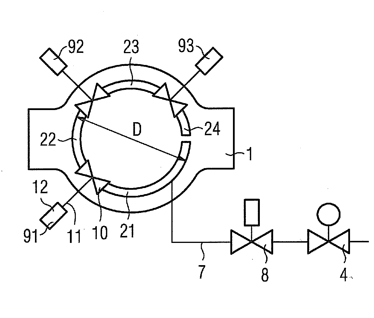
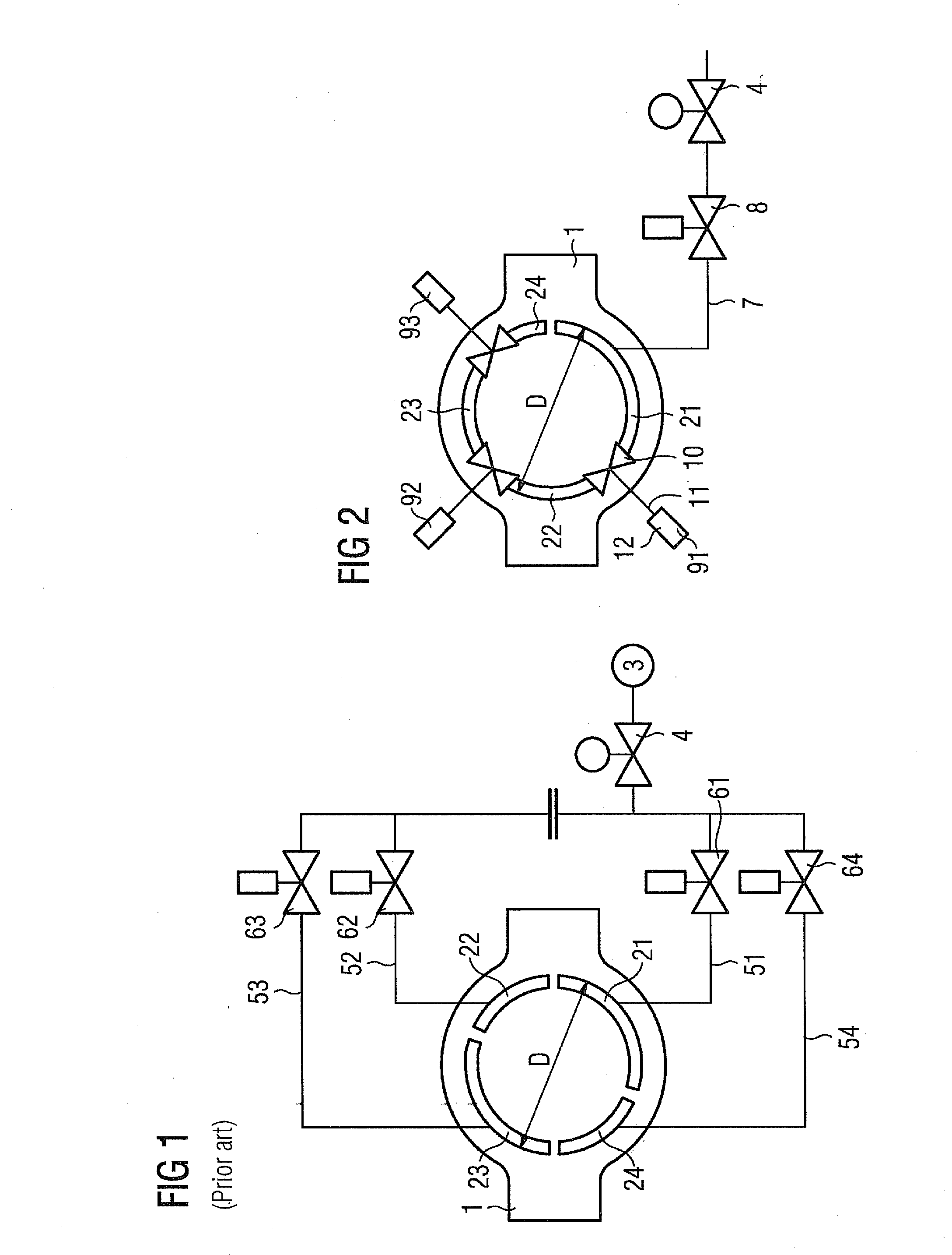
[0022]FIG. 1 shows a schematic diagram of the last circuit of a conventional steam turbine, as is known from the publication mentioned at the start. The housing of the turbine comprises an inflow housing 1 in which the rotor not shown in the diagram is supported to allow rotation. The rotor has working fluid applied to it via four nozzle groups 21, 22, 23, 24 which extend in the shape of an annular sector on a common diameter D around the rotor.

[0023]The working medium—steam in the case of a steam turbine—flows through an inlet 3 into the inflow housing 1. Directly behind the inlet 3 is arranged a quick closing valve 4 through which the inlet 3 can be rapidly closed in an emergency. Behind the quick closing valve 4, the flow fans out in four supply lines 51, 52, 53, 54 which connect the inlet 3 with the nozzle groups 21, 22, 23, 24 in each case. The flow of the working fluid through the supply lines 51, 52, 53, 54 is controlled by respective control valves 61, 62, 63, 64. The nozzle...


PUM


Abstract

A turbine having an inflow housing is provided. The turbine includes an inlet for an inflowing working fluid, wherein the inlet can be closed by a quick closing valve, a plurality of control valves and at least two nozzle groups. The flow of the working fluid is controllable by the inlet into the nozzle groups via the control valves. Furthermore, the inlet can be connected via an inlet line to the first nozzle group, wherein the inlet line is guided through the primary control valve such that the flow of the working fluid along the inlet line can be controlled using the primary control valve. The secondary control valve connects the first nozzle group to the second nozzle group such that the flow of the working fluid from the first nozzle group into the second nozzle group may be controlled using the secondary control valve.

Description

CROSS REFERENCE TO RELATED APPLICATIONS[0001]This application is the US National Stage of International Application No. PCT / EP2008 / 055045, filed Apr. 25, 2008 and claims the benefit thereof. The International Application claims the benefits of European Patent Office application No. 07011268.5 EP filed Jun. 8, 2007, both of the applications are incorporated by reference herein in their entirety.FIELD OF INVENTION[0002]The present invention relates to a turbine with an inflow housing which comprises an inlet for an inflowing working fluid, wherein the inlet can be closed by a quick closing valve, a plurality of control valves and at least two nozzle groups, the flow of the working fluid being controllable from the inlet into the nozzle groups via the control valves.BACKGROUND OF INVENTION[0003]This type of turbine is known from the publication DE 1 915 267 A1 of the same applicant. The inflow housing is the part of the turbine housing into which the working fluid flows into the turbin...

Claims


Application Information

Patent Timeline
Patent Type & Authority Applications(United States)
IPC IPC(8): F01D17/12
CPCF01D17/18F01D17/145
Inventor GEHRINGER, WALTERGEIST, RICHARD
Owner SIEMENS AG
Why Eureka
Try Eureka