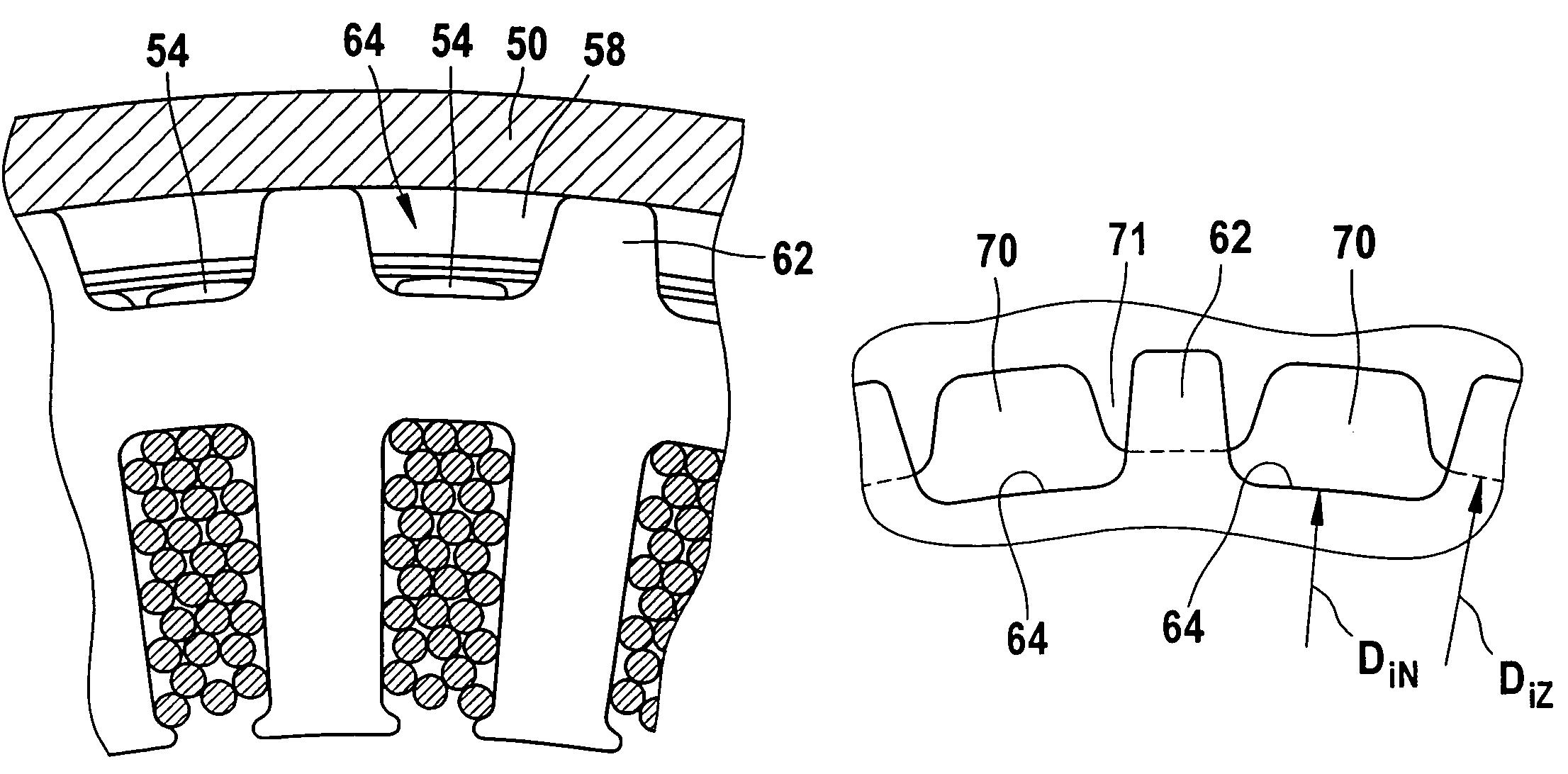
[0003]The electrical machine of the invention having the characteristics of the main claim, in which among other features it is provided that the flow course is defined toward the stator by outer stator teeth located on the outer circumference of the stator, has the
advantage that the cooling area of the stator is markedly increased as a result, and thus the stator can be cooled better on its outer surface.
[0004]It is especially advantageous if outer teeth, extending outward and axially, which define the outer stator slots in the circumferential direction extend from the yoke. This has the
advantage that the yoke is not weakened, but instead its surface area is increased by additional material extending out from the yoke. This improves both the
magnetic flux in the stator iron on the one hand and the convention on the other.
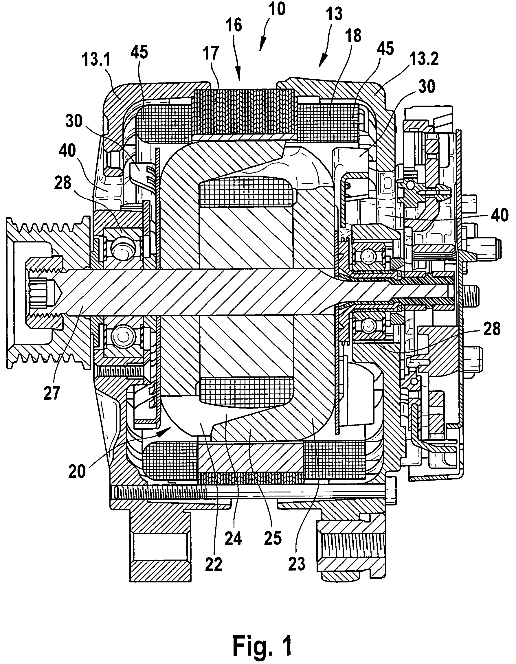
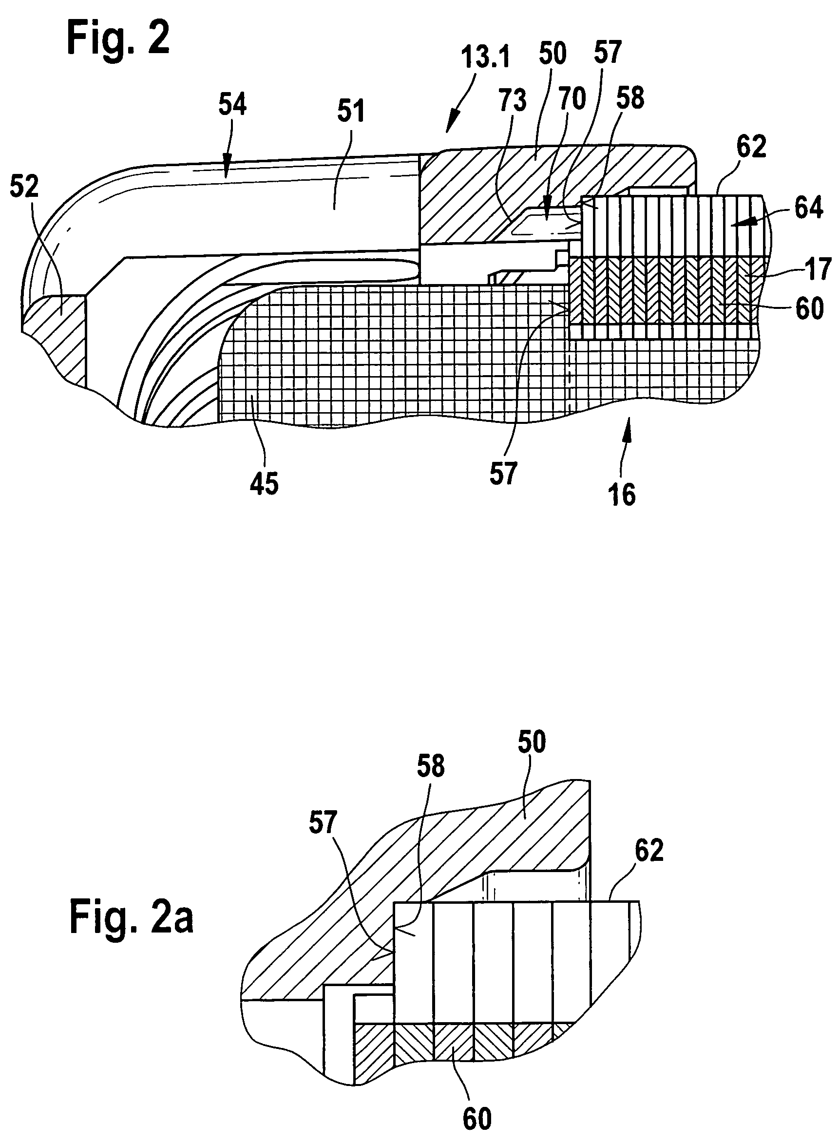
[0006]A further improvement in the invention is obtained by providing that a housing part, for instance a bearing plate, adjacent to the stator has a toothed or slotted end face, and housing slots are diametrically opposite the outer stator slots. By this provision, an improved guidance of the flow in the circumferential region, that is, at the interface between stator and bearing plate, is made possible, since because of the toothed or slotted end face, additional conduits or flow possibilities are opened up, and thus the flow resistance in this region drops further. The volumetric flow for the
coolant can thus be further increased, and as a result the temperature of the stator drops.
[0007]For adjusting the desired quantity of cooling air in the region of the contact face between the stator and the housing part, it is provided that the housing slots extend in an annular region of the housing part and also end in that region. In addition, via the design, for instance with regard to the length of these housing slots, the stability of the annular region is also influenced in terms of its vibration properties and thus its
vulnerability to breakage. If the housing slots did not end in the annular region, the housing part would be weakened too greatly. It is provided that the housing slots end with a chamfer. This has the advantage that the effective flow cross section is especially large at the transition from the region outside the winding heads of the stator iron or stator to the housing part. As a result, the flow can be guided better. Moreover, the risk that these openings will become soiled and thus plugged up is lessened.
[0006]A further improvement in the invention is obtained by providing that a housing part, for instance a bearing plate, adjacent to the stator has a toothed or slotted end face, and housing slots are diametrically opposite the outer stator slots. By this provision, an improved guidance of the flow in the circumferential region, that is, at the interface between stator and bearing plate, is made possible, since because of the toothed or slotted end face, additional conduits or flow possibilities are opened up, and thus the flow resistance in this region drops further. The volumetric flow for the coolant can thus be further increased, and as a result the temperature of the stator drops.
[0009]For improved flow guidance, it is provided that the continuous annular region extends for at least 20% up to approximately 70% of its total
axial length over the stator. Thus the continuous annular region covers a certain length of the stator, or of its outer stator teeth. As a result, the cooling air can flow over the surface of the outer stator teeth longer, and the
cooling effect for the stator or stator iron is thus improved.
[0010]The vibration properties of the housing part are furthermore improved by this coverage of the stator.
[0011]For further improvement, it is provided that the housing teeth are wider in the circumferential direction than the outer stator teeth.
[0012]To further optimize the
heat transfer or flow properties, it is provided that the outer stator teeth are covered by housing teeth in a first approximation over a radial length of 40% to 70%. In a second approximation, it is provided that this coverage amounts to between 50% to 64%.

