
Piping structure with inner heat exchanger and refrigeration cycle device having the same

Inactive Publication Date: 2007-11-01
DENSO CORP
View PDF5 Cites 13 Cited by
  • Summary
  • Abstract
  • Description
  • Claims
  • Application Information

AI Technical Summary

Benefits of technology

[0008]In view of the foregoing problems, it is an object of the present invention to provide a piping structure an

Problems solved by technology

However, in an air conditioner for a vehicle (dual air conditioner) provided with the plural evaporators, for example, for a front seat and a rear seat, when a low-pressure refrigerant pipe from each of the evaporators is made to communicate with a low-pressure refrigerant pipe of a double pipe part, there is presented a problem that a pressure loss in the low-pressure refrigerant pipe of the double pipe part increases depending on the shape of the double pipe part thereby decreasing a cooling capacity.

Method used


Image

  • Piping structure with inner heat exchanger and refrigeration cycle device having the same
  • Piping structure with inner heat exchanger and refrigeration cycle device having the same
  • Piping structure with inner heat exchanger and refrigeration cycle device having the same

Examples


first embodiment

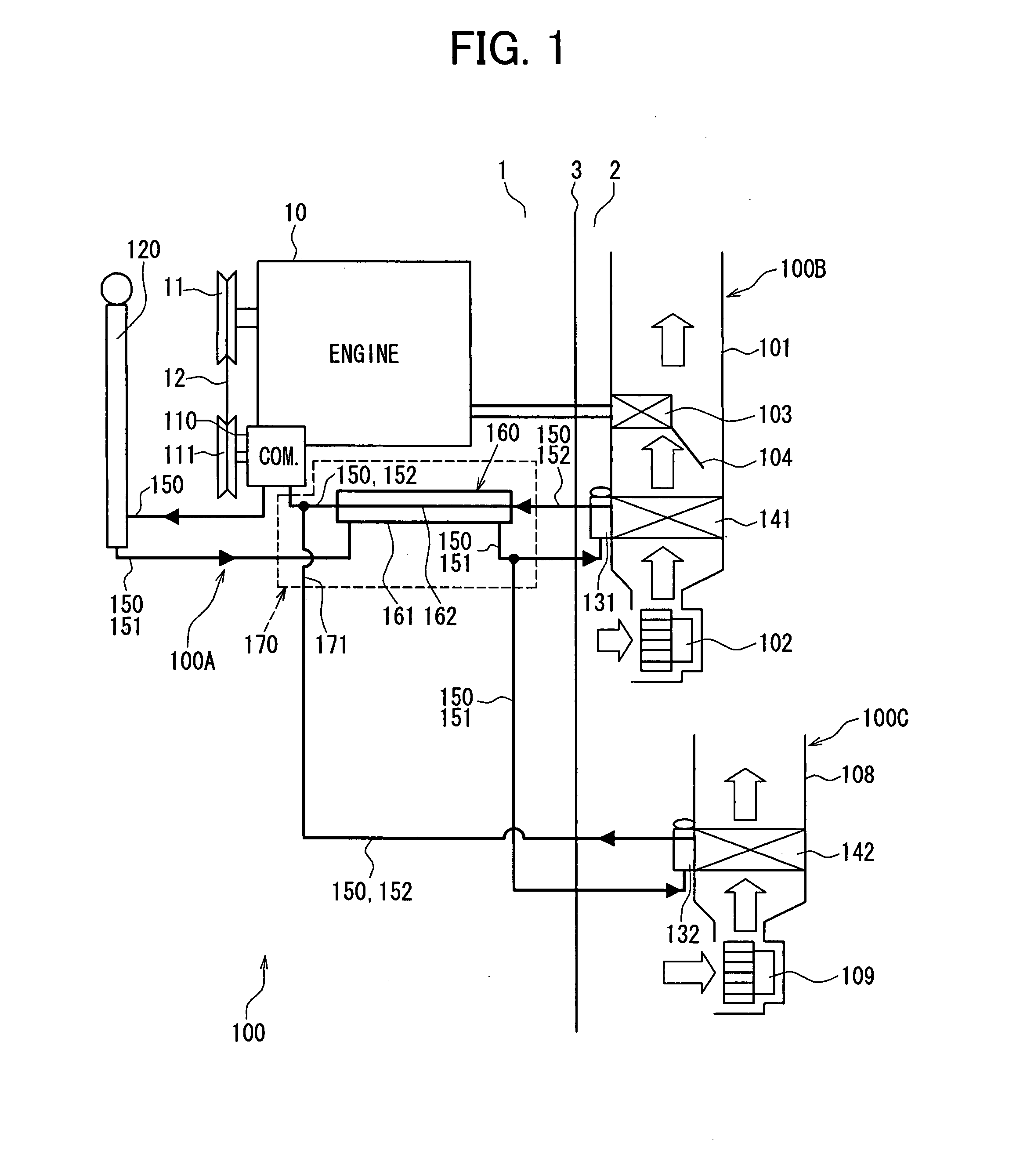
[0026]In this embodiment, a piping structure 170 with an inner heat exchanger in accordance with the present invention and a refrigeration cycle device 100A using the same are typically used for an air conditioner for a vehicle (hereinafter referred to as air conditioner) 100.

[0027]As shown in FIG. 1, a vehicle is partitioned by a dash panel 3 into an engine room 1 in which an engine 10 for a vehicle running is mounted and a vehicle compartment 2 for occupants. Among a refrigeration cycle device 100A and interior units 100B, 100C which construct the air conditioner 100, a part of the refrigeration cycle device 100A (except for expansion valves 131, 132, and evaporators 141, 142 as low-pressure side heat exchangers) is disposed in the engine room 1. The air conditioner 100 in this embodiment is a dual air conditioner provided with two interior units 100B, 100C for the front seat and the rear seat of the vehicle. The interior unit 100B for the front seat is disposed in an instrument p...

second embodiment

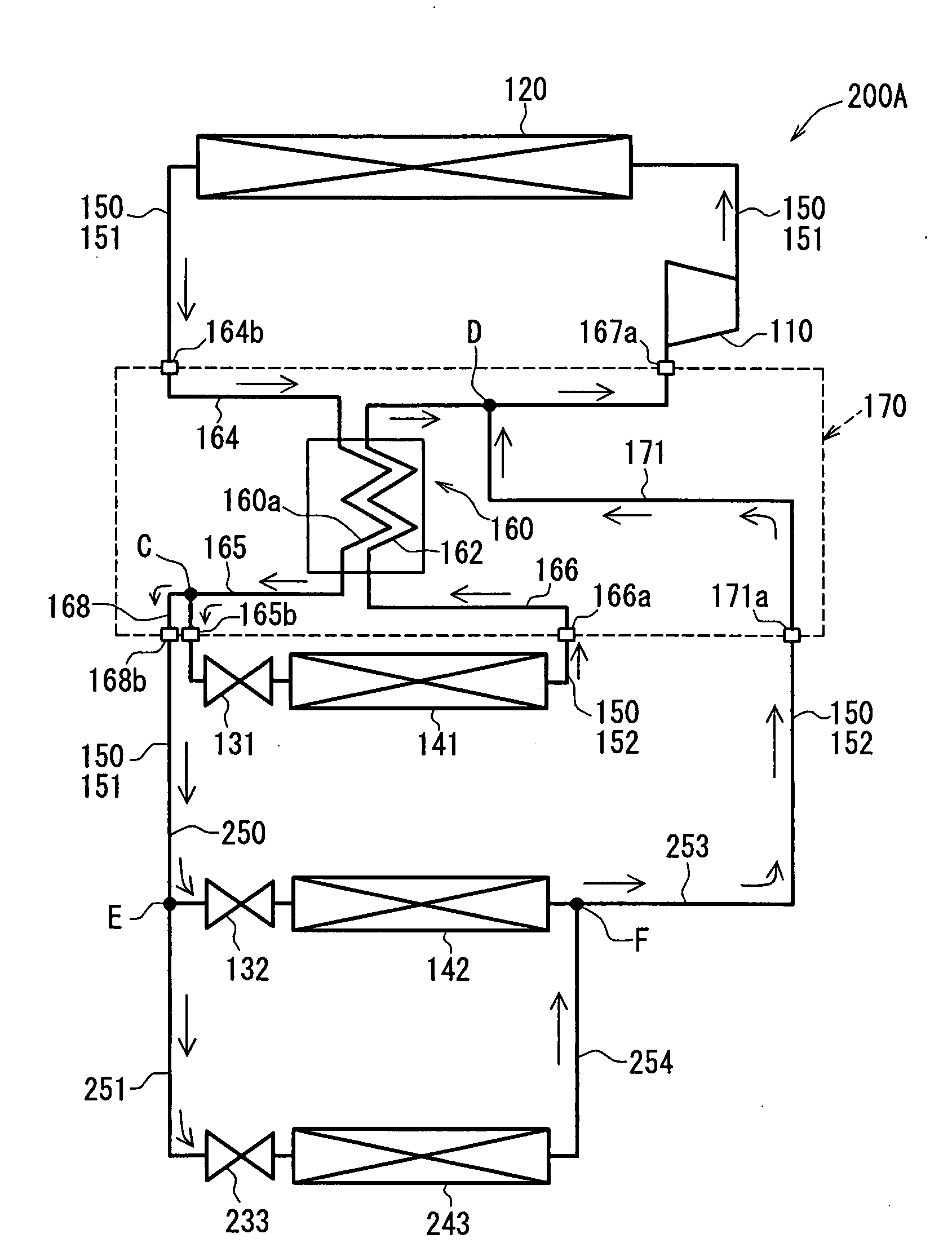
[0056]A second embodiment of the present invention will be described with reference to FIG. 9. In the above-described first embodiment, the piping structure 170 with the inner heat exchanger is applied to the refrigeration cycle device 100A of the dual air conditioner 100 that are provided with the two evaporators 141, 142 for the front seat and the rear seat. In contrast to this, in this embodiment, the piping structure 170 with the inner heat exchanger of the present invention is applied to a refrigeration cycle device 200A of an air conditioner for a vehicle (triple air conditioner) provided with three evaporators 141, 142, and 243 for the front seat, the rear seat, and a cool box.

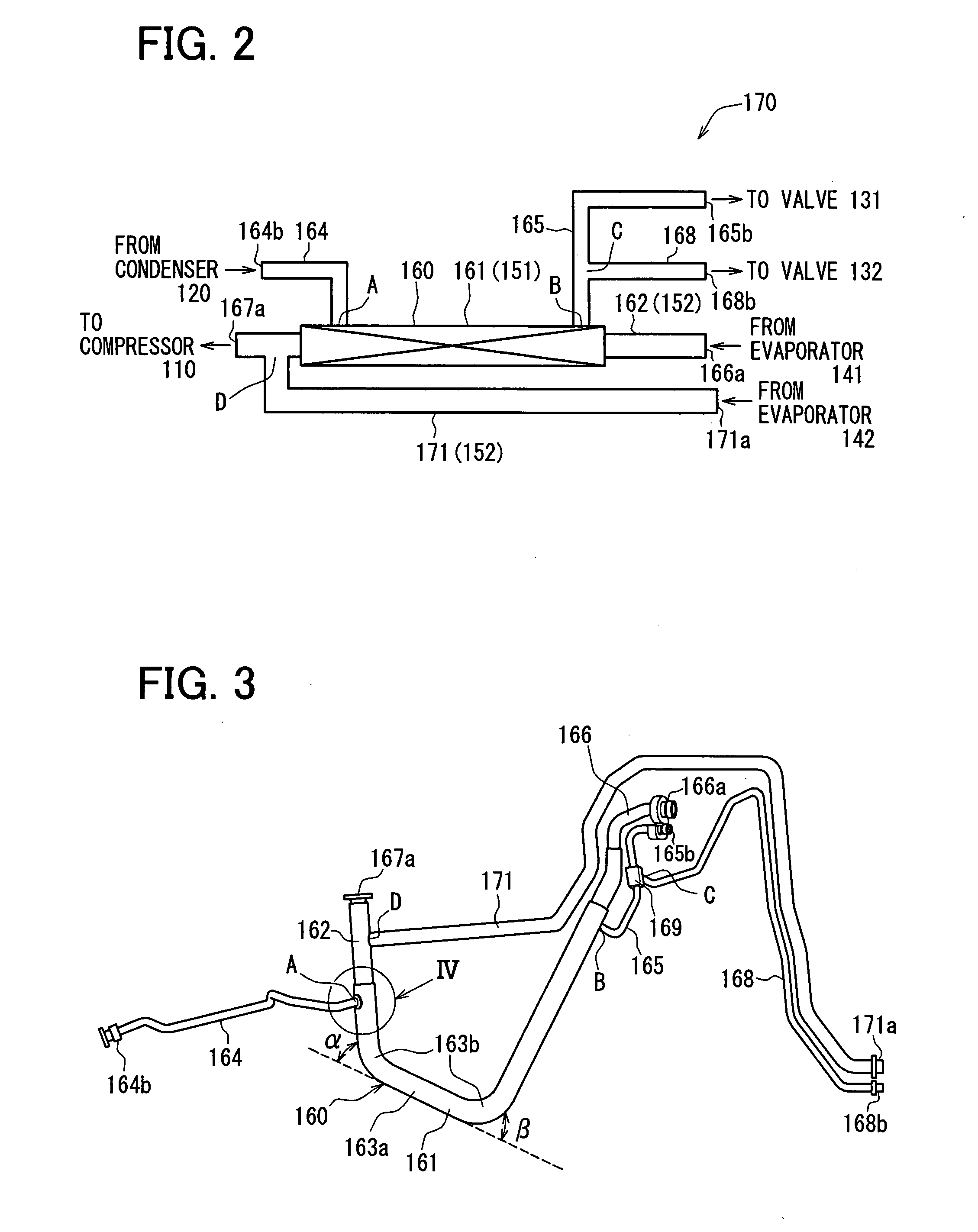
[0057]The piping structure 170 with the inner heat exchanger in this embodiment has the same construction as in the first embodiment shown in FIG. 2 to FIG. 4, and the condenser 120, the compressor 110, the front expansion valve 131, the front evaporator 141 are connected to the joints 164b, 167a, 165b,...


PUM


Abstract

A piping structure for a refrigerant cycle device includes an inner heat exchanger, and a bypass pipe through which refrigerant flows while bypassing the inner heat exchanger. The inner heat exchanger has a first flow passage in which high-pressure refrigerant before being decompressed flows and a second flow passage in which low-pressure refrigerant after being decompressed flows. The refrigerant cycle device includes plural low-pressure side heat exchangers, and the plural low-pressure side heat exchangers are located such that refrigerant from a part of the low-pressure side heat exchangers flows through the second flow passage of the inner heat exchanger, and refrigerant from the other part of the low-pressure side heat exchangers flows through the bypass pipe while bypassing the inner heat exchanger.

Description

CROSS REFERENCE TO RELATED APPLICATION[0001]This application is based on Japanese Patent Application No. 2006-124740 filed on Apr. 28, 2006, the contents of which are incorporated herein by reference in its entirety.BACKGROUND OF THE INVENTION[0002]1. Field of the Invention[0003]The present invention relates to a piping structure with an inner heat exchanger and a refrigeration cycle device provided with the same.[0004]2. Description of the Related Art[0005]Piping for a refrigeration cycle device for a vehicle air conditioner has been known as a piping structure provided with an inner heat exchanger. This piping for a refrigeration cycle device has a double pipe structure as an inner heat exchanger, as described in JP-A-2001-277842 (corresponding to U.S. Pat. No. 6,866,090), for example. The double pipe structure has a high-pressure refrigerant pipe extending from a compressor to an evaporator via a condenser and a low-pressure refrigerant pipe extending from the evaporator to the c...

Claims


Application Information

Patent Timeline
IPC IPC(8): F25B41/00F25B41/06
CPCB60H1/323F25B5/02F25B2500/01F25B2400/0417F25B2400/0419F25B40/00
Inventor KURATA, SHUNAIZAWA, HIDEOSUZUKI, TAKAHISA
Owner DENSO CORP
Learn More