Method and apparatus for operating gas turbine engines

a gas turbine engine and gas turbine technology, applied in the direction of machines/engines, non-positive displacement fluid engines, pump control, etc., can solve the problems of adversely affecting engine performance, thermal expansion or contraction of the rotor and stator assembly, and inability to occur uniformly in magnitude or rate, so as to facilitate the reduction of pressure losses of airflow into the inlet assembly and facilitate the reduction of pressure losses

Active Publication Date: 2010-05-18
GENERAL ELECTRIC CO
View PDF13 Cites 12 Cited by
  • Summary
  • Abstract
  • Description
  • Claims
  • Application Information

AI Technical Summary

Benefits of technology

[0005]In one aspect, a method for operating a gas turbine engine is provided. The gas turbine engine includes a fan, a high pressure turbine coupled downstream from the fan, and a low pressure turbine downstream from the high pressure turbine. The method includes channeling a portion of air discharged from the fan through a clearance control system including an inlet assembly that includes a plurality of louvers, and directing air from the inlet assembly into a first pipe and a second pipe coupled to the inlet assembly such that pressure losses associated with the airflow are facilitated to be reduced.
[0006]In a further aspect, a turbine assembly is provided. The turbine assembly includes a first rotor assembly including a first case manifold, a second rotor assembly including a second case manifold wherein the second rotor assembly is disposed downstream from the first rotor assembly. The turbine assembly also includes a clearance control system coupled within the turbine assembly and located upstream from the first and second rotor assemblies. The clearance control system includes an inlet assembly, an inlet tube, a first transfer pipe, and a second transfer pipe. The inlet assembly includes a plurality of louvers oriented to direct cooling air into the clearance control system. The inlet tube is coupled to the inlet assembly. The first pipe and the second pipe are coupled in flow communication to the inlet tube such that substantially all of the cooling air discharged from the inlet assembly is channeled into the first and second pipes such that pressure losses of the airflow entering the inlet assembly are facilitated to be reduced.
[0007]In a further aspect, a clearance control system for use with a gas turbine engine assembly including a fan, a first rotor assembly downstream from the fan, and a second rotor assembly downstream from the first rotor assembly is provided. The system includes an inlet assembly including a plurality of louvers oriented to channel air discharged from the fan into the inlet assembly. The system also includes a first pipe extending downstream from the inlet assembly and configured to couple to a portion of the high pressure turbine. The system also includes a second pipe extending downstream from the inlet assembly for channeling air discharged from the inlet assembly towards the second rotor assembly. The clearance control system facilitates active clearance control between the first and second rotor assemblies and a stationary component positioned adjacent to the first and second rotor assemblies.

Problems solved by technology

During engine operation, the thermal environment variations in the engine may cause thermal expansion or contraction of the rotor and stator assemblies.
Such thermal expansion or contraction may not occur uniformly in magnitude or rate.
As a result, inadvertent rubbing, such as between the rotor blade tips and the casing may occur, or radial clearances may be created that are wider than the design clearances which may adversely affect engine performance.
Continued rubbing between the rotor blade tips and engine casing may lead to premature failure of the rotor blade.

Method used


Image

  • Method and apparatus for operating gas turbine engines
  • Method and apparatus for operating gas turbine engines
  • Method and apparatus for operating gas turbine engines

Examples


Embodiment Construction

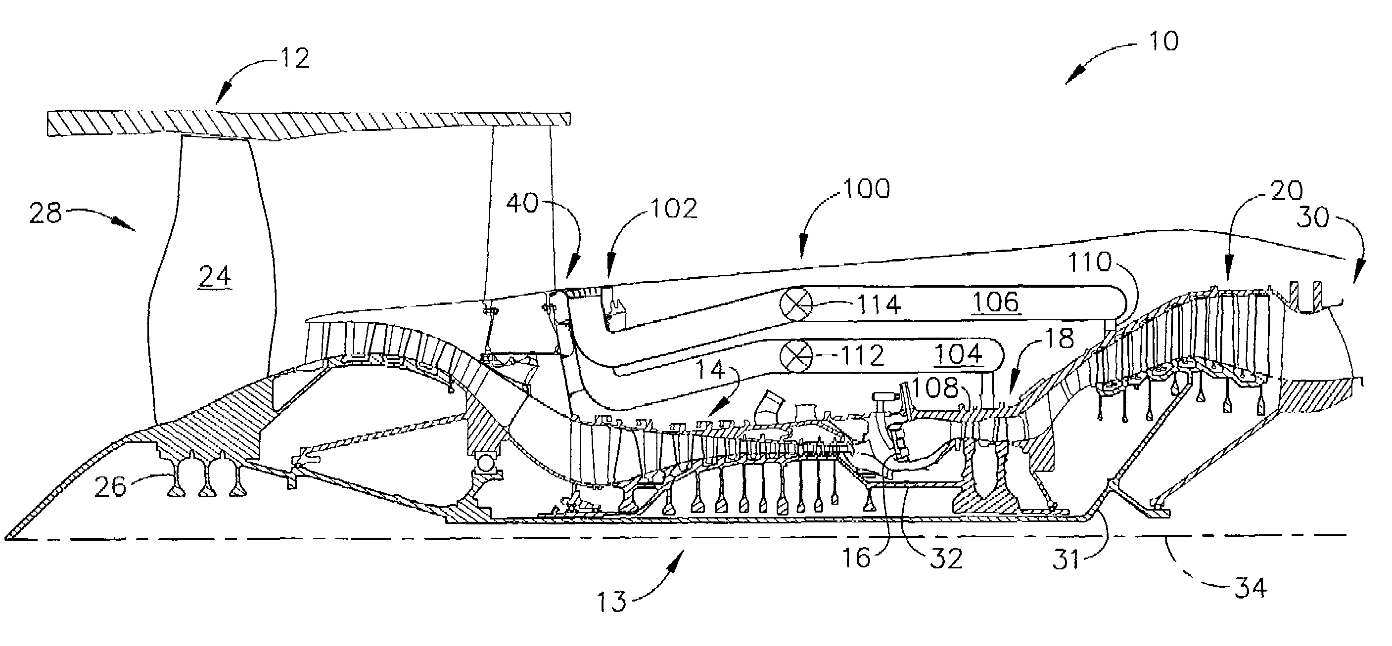
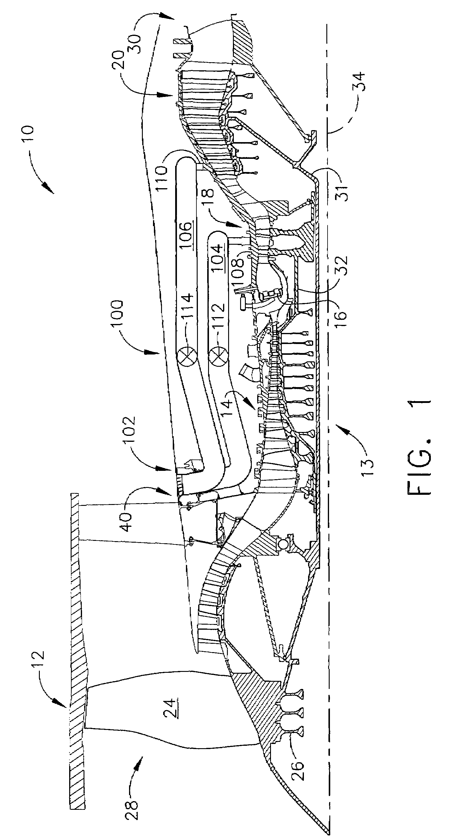
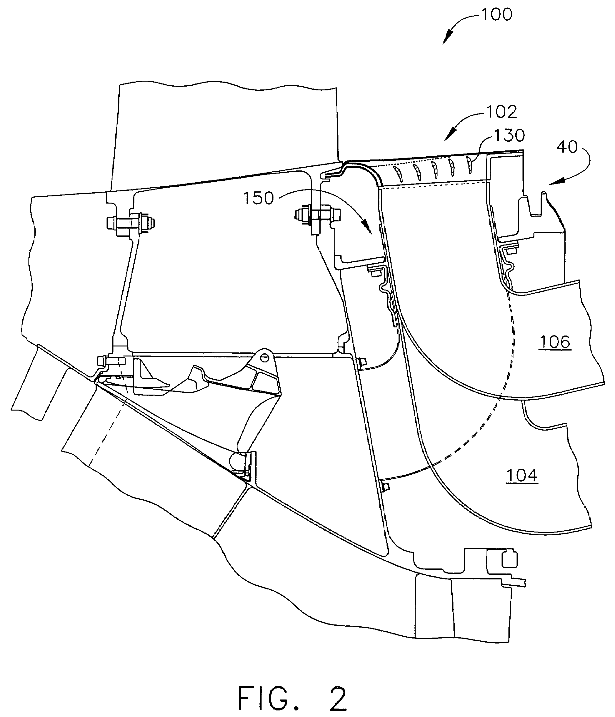
[0013]FIG. 1 is a schematic illustration of an exemplary gas turbine engine 10 that includes a fan assembly 12 and a core engine 13 including a high pressure compressor 14, a combustor 16, and a high pressure turbine 18. Engine 10 also includes a low pressure turbine 20. Fan assembly 12 includes an array of fan blades 24 that extend radially outward from a rotor disk 26. Engine 10 has an intake side 28 and an exhaust side 30. Fan assembly 12 and low pressure turbine 20 are coupled by a low speed rotor shaft 31, and compressor 14 and high pressure turbine 18 are coupled by a high speed rotor shaft 32.

[0014]Generally, during operation, air flows axially through fan assembly 12, in a direction that is substantially parallel to a central axis 34 extending through engine 10, and compressed air is supplied to high pressure compressor 14. The highly compressed air is delivered to combustor 16. Combustion gas flow (not shown in FIG. 1) from combustor 16 drives turbines 18 and 20. Turbine 18...


PUM


Abstract

A method for operating a gas turbine engine is provided. The gas turbine engine includes a fan, a high pressure turbine coupled downstream from the fan, and a low pressure turbine downstream from the high pressure turbine. The method includes channeling a portion of air discharged from the fan through a clearance control system including an inlet assembly that includes a plurality of louvers, and directing air from the inlet assembly into a first pipe and second pipe coupled to the inlet assembly such that pressure losses associated with the airflow are facilitated to be reduced.

Description

BACKGROUND OF THE INVENTION[0001]This invention relates generally to turbine engines and more specifically to clearance control systems used with gas turbine engines.[0002]Known gas turbine engines include an engine casing that extends circumferentially around a compressor, and a turbine that includes a rotor assembly and a stator assembly. Known rotor assemblies include at least one row of rotating blades that extend radially outward from a blade root to a blade tip. A radial tip clearance is defined between the rotating blade tips and a stationary shroud attached to the engine casing.[0003]During engine operation, the thermal environment variations in the engine may cause thermal expansion or contraction of the rotor and stator assemblies. Such thermal expansion or contraction may not occur uniformly in magnitude or rate. As a result, inadvertent rubbing, such as between the rotor blade tips and the casing may occur, or radial clearances may be created that are wider than the desi...

Claims


Application Information

Patent Timeline
Patent Type & Authority Patents(United States)
IPC IPC(8): F04D31/00F01D11/24
CPCF01D11/24F01D11/14
Inventor URBASSIK, RYAN MICHAELESTRIDGE, SCOTT ANTHONYRUIZ, RAFAELPROCTOR, ROBERTALBERS, ROBERT J.HANSELL, KEVIN STEPHEN
Owner GENERAL ELECTRIC CO
Why Eureka
Try Eureka