Vortex reducer in the high-pressure compressor of a gas turbine

a gas turbine and compressor technology, applied in the direction of machines/engines, mechanical equipment, liquid fuel engines, etc., can solve the problems of pressure loss and dissipation of secondary air tubes, and achieve the effect of reducing deflection pressure loss and smooth deflection of secondary air tubes

Inactive Publication Date: 2007-01-09
ROLLS ROYCE DEUT LTD & CO KG
View PDF26 Cites 50 Cited by
  • Summary
  • Abstract
  • Description
  • Claims
  • Application Information

AI Technical Summary

Benefits of technology

[0020]Also, the effective deflection surfaces are not intended to be limited to the plane or truncated-cone shape. Giving these surfaces a three-dimensional or curved shape, similar to the curvature of the outlet tube, will deflect the secondary air more smoothly, thus providing for further reduction of the deflection pressure loss.

Problems solved by technology

These designs are disadvantageous in that the vortex formation at the exit of the secondary air tubes entails pressure losses and dissipation.

Method used


Image

  • Vortex reducer in the high-pressure compressor of a gas turbine
  • Vortex reducer in the high-pressure compressor of a gas turbine
  • Vortex reducer in the high-pressure compressor of a gas turbine

Examples


Embodiment Construction

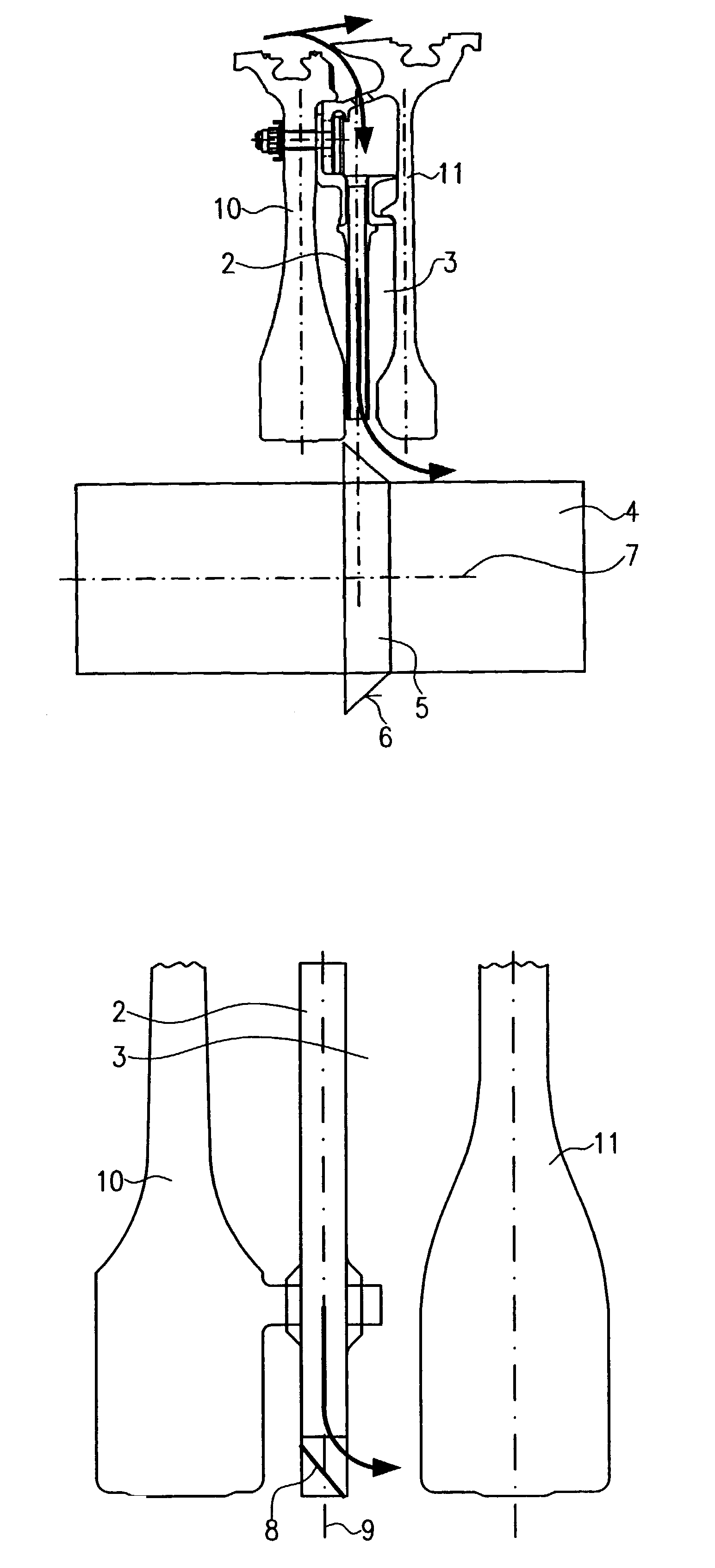
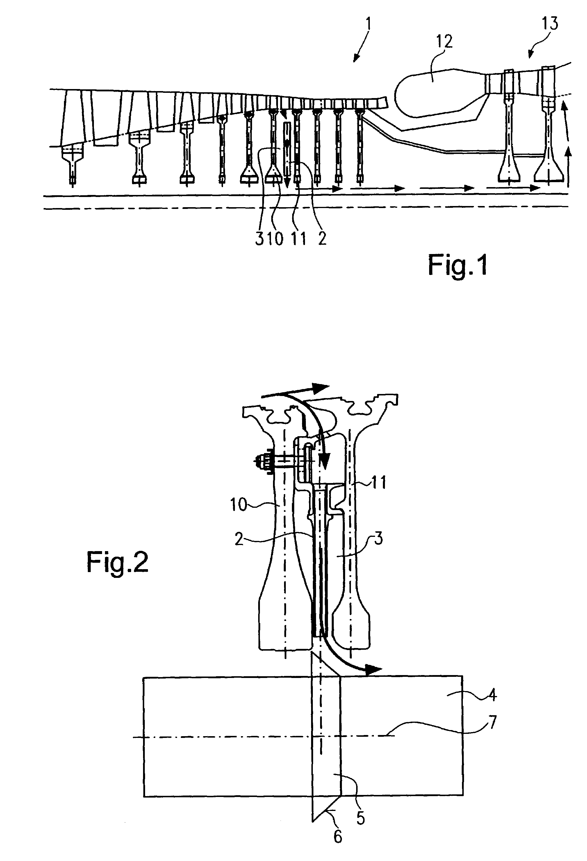
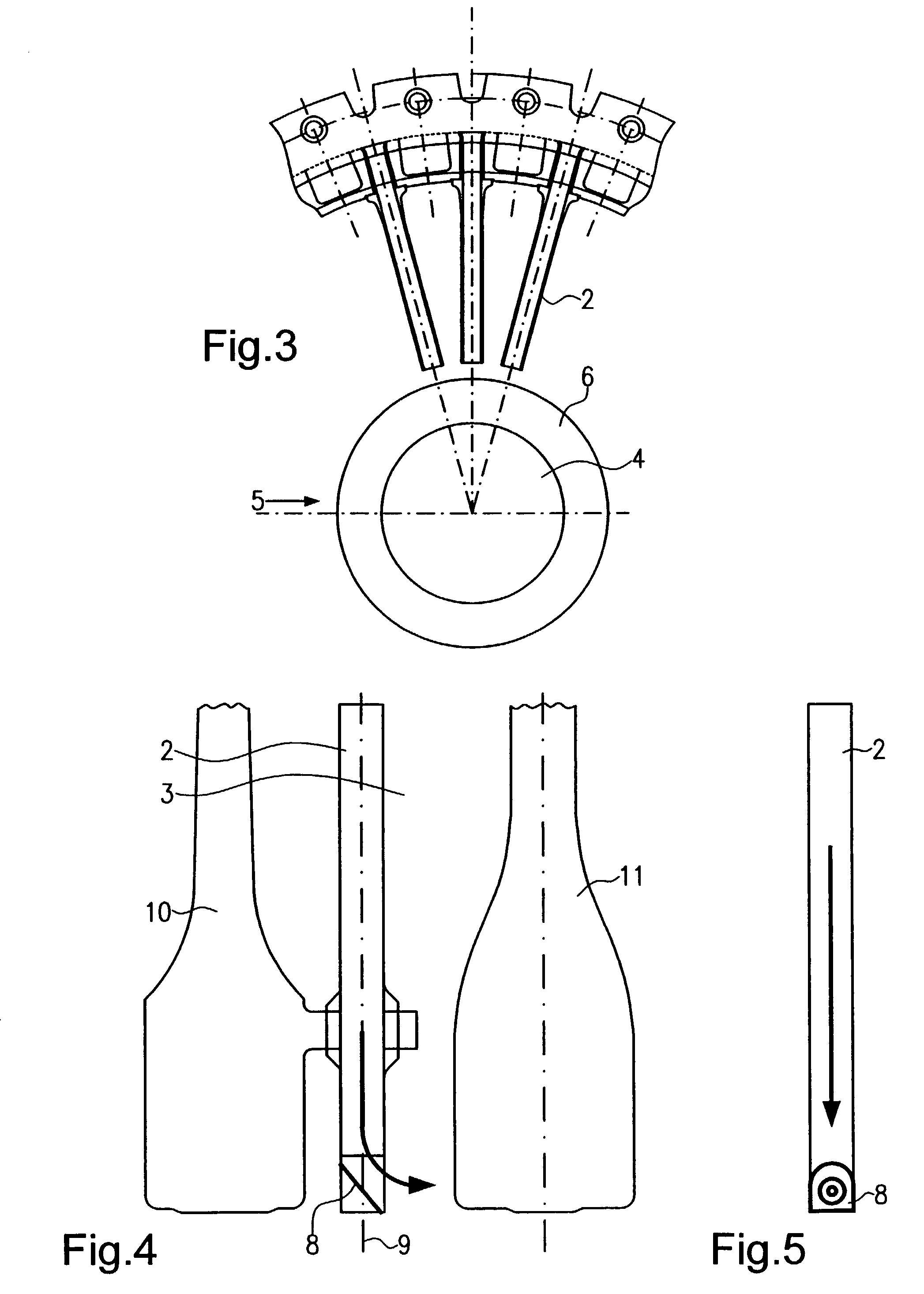
[0031]FIG. 1 shows, in schematic representation, a partial area of a gas turbine. Reference numeral 1 indicates a compressor which comprises several compressor disks or rotor disks. Reference numeral 10 indicates a compressor disk of stage 6, while reference numeral 11 indicates a compressor disk of stage 7, for example. These disks form a disk interspace 3 in which a plurality of radially arranged secondary air tubes 2 (see also FIG. 3) are provided. The arrangement and design of the secondary air tubes 2 is known from the prior art, so that a detailed description is dispensed with herein. FIG. 1 further shows, in schematic representation, a combustion chamber 12 and, also in schematic representation, a turbine 13. FIG. 1 also illustrates the cooling airflows in highly simplified manner. As these flows are also known from the prior art, a further description is again dispensed with herein.

[0032]FIG. 2 shows a first embodiment of the present invention. A deflector ring 5 is here fit...


PUM


Abstract

A tube-type vortex reducer for the conduction of cooling air in a compressor 1 of a gas turbine with at least one radial secondary air tube 2 arranged in a disk interspace 3, includes a deflector arranged in a discharge area of the secondary air tube for the deflection of the secondary air flow into an axial direction or away from an axial direction.

Description

[0001]This application claims priority to German Patent Application DE10159670.7 filed Dec. 5, 2001, the entirety of which is incorporated by reference herein.BACKGROUND OF THE INVENTION[0002]This invention relates to a tube-type vortex reducer for a high-pressure compressor of a gas turbine.[0003]More particularly, this invention relates to a vortex reducer in which secondary air tubes are arranged in a disk interspace.[0004]The use of secondary air tubes for the conduction of the secondary air flow in a disk interspace is known from the prior art. Such designs are described in general terms in Specifications DE 26 33 222 A1 or U.S. Pat. No. 3,043,561, for example.[0005]These designs are disadvantageous in that the vortex formation at the exit of the secondary air tubes entails pressure losses and dissipation.BRIEF SUMMARY OF THE INVENTION[0006]In a broad aspect, the present invention provides a vortex reducer of the type described above which avoids the disadvantages of the state ...

Claims


Application Information

Patent Timeline
Patent Type & Authority Patents(United States)
IPC IPC(8): F02C6/04F01D5/08
CPCF01D5/081F01D5/085F05D2260/20F04D29/321
Inventor HEIN, STEFANSTEIN, MANUELAPEITSCH, DIETER
Owner ROLLS ROYCE DEUT LTD & CO KG
Why Eureka
Try Eureka