
Movable arm deflection system of excavator, excavator and movable arm deflection control method thereof

A deflection system, excavator technology, applied in mechanically driven excavators/dredgers, etc., can solve problems such as increased operation difficulty, collision between work equipment and obstacles, property damage, etc., to reduce safety risks, reduce operation difficulty, The effect of improving work efficiency

Active Publication Date: 2021-01-22
XCMG EXCAVATOR MACHINERY
View PDF21 Cites 1 Cited by
  • Summary
  • Abstract
  • Description
  • Claims
  • Application Information

AI Technical Summary

Problems solved by technology

The above-mentioned way of stepping on the pilot foot valve is easy to form an impact, resulting in an unsteady movement of the boom, and the angle of the boom can only be adjusted according to experience, which increases the difficulty of operation, and may also cause the working device of the excavator to collide with obstacles, resulting in Safety risk of property damage or even personal injury

Method used


Image

  • Movable arm deflection system of excavator, excavator and movable arm deflection control method thereof
  • Movable arm deflection system of excavator, excavator and movable arm deflection control method thereof
  • Movable arm deflection system of excavator, excavator and movable arm deflection control method thereof

Examples


Embodiment Construction

[0050] The following will clearly and completely describe the technical solutions in the embodiments of the present disclosure with reference to the accompanying drawings in the embodiments of the present disclosure. Apparently, the described embodiments are only some of the embodiments of the present disclosure, not all of them. The following description of at least one exemplary embodiment is merely illustrative in nature and in no way intended as any limitation of the disclosure, its application or uses. Based on the embodiments in the present disclosure, all other embodiments obtained by persons of ordinary skill in the art without creative efforts fall within the protection scope of the present disclosure.

[0051] Relative arrangements of components and steps, numerical expressions and numerical values ​​set forth in these embodiments do not limit the scope of the present disclosure unless specifically stated otherwise. At the same time, it should be understood that, for...


PUM


Abstract

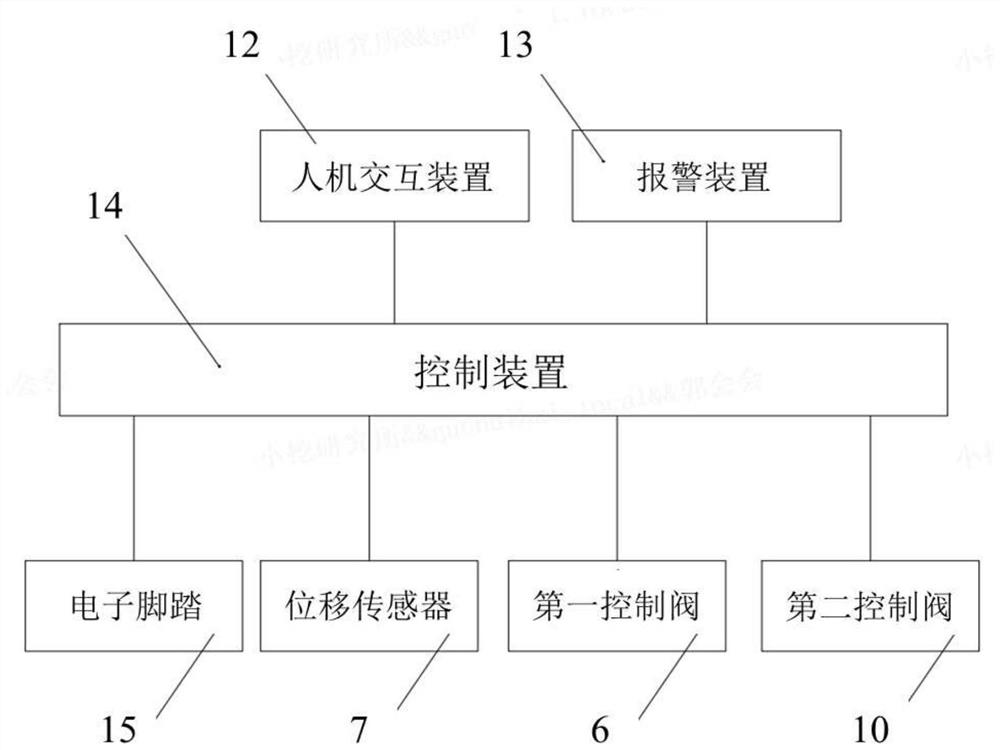
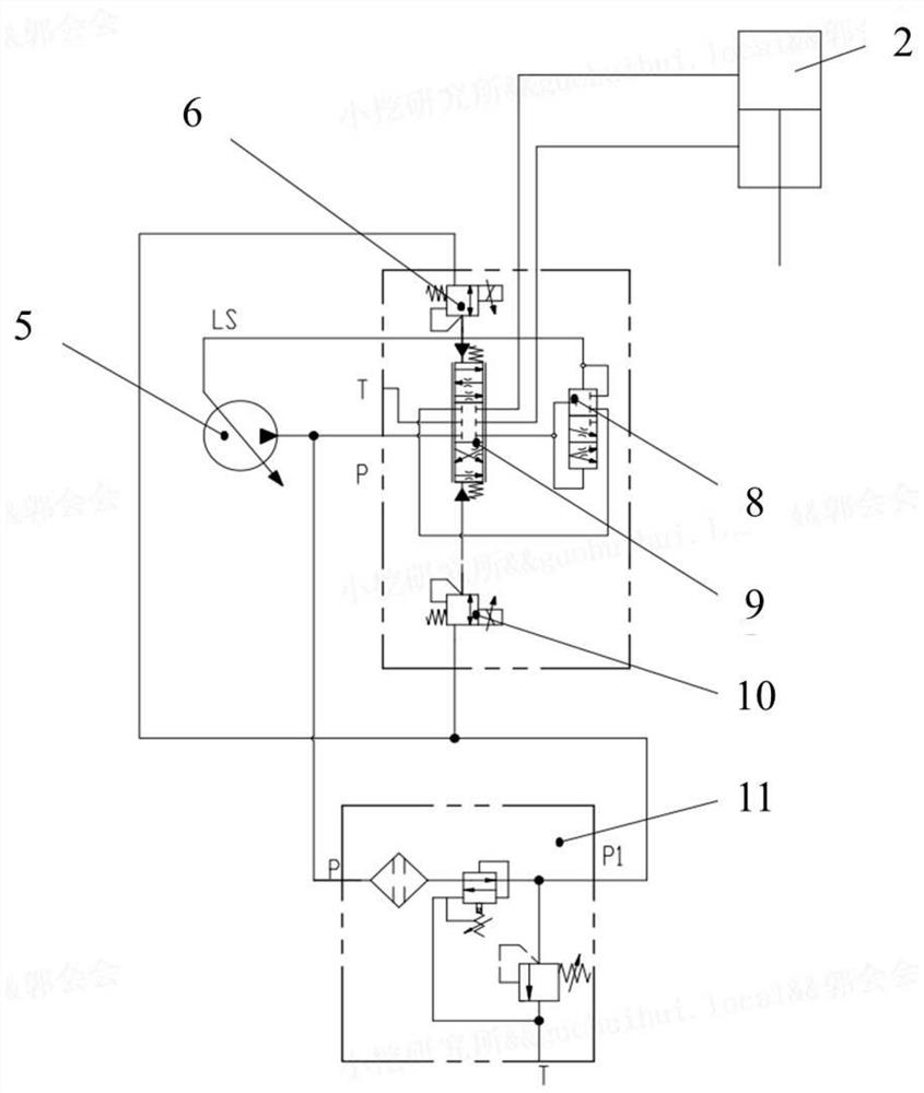
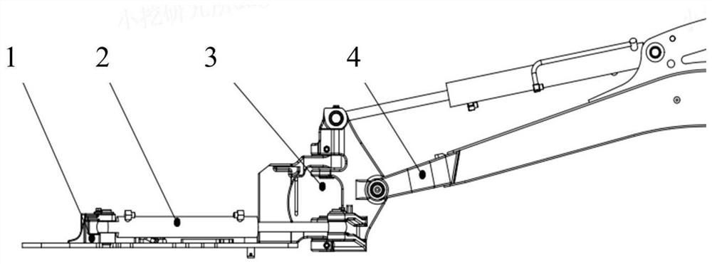
The invention provides a movable arm deflection system of an excavator, the excavator and a movable arm deflection control method thereof. The movable arm deflection system includes a hydraulic pump,a movable arm deflection mechanism which comprises a movable arm and a deflection oil cylinder, a control valve group, a detection device and a control device; the control valve group comprises a distribution valve used for controlling the deflection direction of the movable arm, a first control valve and a second control valve, the first control valve and the second control valve are used for controlling the position of a valve element of a distribution valve to enable the movable arm to deflect towards a first direction and a second direction opposite to the first direction respectively; thedetection device is used for acquiring detection information reflecting a real-time deflection angle of the movable arm; and the control device is used for controlling the position of the valve element of the first control valve and the second control valve according to the detection information so as to enable the movable arm to be in a deflection range allowed by an operation area. The movablearm deflection control method comprises the steps that the real-time deflection angle of the movable arm is obtained; and when the real-time deflection angle is equal to or larger than the maximum deflection angle in the first direction or the maximum deflection angle in the second direction, the corresponding control valves are cut off. According to the movable arm deflection system of the excavator, the excavator and the movable arm deflection control method, the safety risk of the excavator during operation in a narrow area can be reduced.

Description

technical field [0001] The present disclosure relates to the technical field of excavators, and in particular to an excavator boom deflection system, the excavator and a boom deflection control method thereof. Background technique [0002] As an important construction machine, the excavator can realize 360-degree rotary operation and is widely used in various earthwork operations. However, in some narrow areas, the turning angle of the excavator is limited, which affects the normal operation of the excavator. In order to adapt to the narrow working area, most excavators are equipped with the boom deflection function. By adjusting the angle of the boom, the adjustment of the working position of the excavator can be realized, which reduces the impact of the narrow working area on the construction of the excavator. [0003] In related technologies, the main solution to realize the boom deflection function is to control the movement of the distribution valve spool through the p...

Claims


Application Information

Patent Timeline
Patent Type & Authority Applications(China)
IPC IPC(8): E02F3/38E02F3/42
CPCE02F3/38E02F3/42Y02A20/204
Inventor 郭会会马立国于书敏周威刘跃吉张飞崔奇王荣标王震史光程
Owner XCMG EXCAVATOR MACHINERY
Learn More