Screw compressors with rotor and casing design for controlling deflections

a compressor and rotor technology, applied in the direction of liquid fuel engines, vessel construction, marine propulsion, etc., can solve the problems of loss of efficiency, rubbing and potential failure, and the inability to achieve such zero clearance, so as to reduce the deflection of compressor components, minimize the variation of clearance during compressor operation, and even out the effect of deflection

Inactive Publication Date: 2005-04-19
CARRIER CORP
View PDF1 Cites 2 Cited by
  • Summary
  • Abstract
  • Description
  • Claims
  • Application Information

AI Technical Summary

Benefits of technology

[0007]In accordance with one aspect of the invention, the screw rotor pressure load distribution is modified so as to provide a resultant load due to operation of the compressor which is smaller in magnitude and which act on said rotor at a point closer to the discharge end bearing. This helps to reduce deflection of compressor components so as to minimize variation in clearance during compressor operation in accordance with the present invention.
[0008]In accordance with a further aspect of the present invention, the suction end of the rotor is adapted to be more flexible than the discharge end, preferably by providing the suction end of the rotor or rotor shaft in hollow form such that the smaller load at this portion of the shaft will produce substantially the same amount of deflection or distortion as is provided by the larger load at the discharge pressure end, which is applied to a solid rotor end shaft. This advantageously evens out deflection due to operation within the expected operating envelope, further facilitating minimization of variation in clearance in the operating envelope.
[0009]In accordance with another aspect of the present invention, additional thermal masses are positioned at desirable locations, particularly on the compressor housing, so as to reduce thermal distortions of compressor components or provide for thermal distributions that will compensate for load deflections, thus reducing clearance and variance in clearance.

Problems solved by technology

Excessive clearance between screw rotors and the housing results in loss of efficiency, while insufficient clearance results in rubbing and potential failures due to scoring or excessive wear of compressor components.
Of course, it is impossible to achieve such zero clearance as different operating conditions subject the compressor to different stresses and forces which cause the clearance to vary across the rotor length.

Method used


Image

  • Screw compressors with rotor and casing design for controlling deflections
  • Screw compressors with rotor and casing design for controlling deflections
  • Screw compressors with rotor and casing design for controlling deflections

Examples


Embodiment Construction

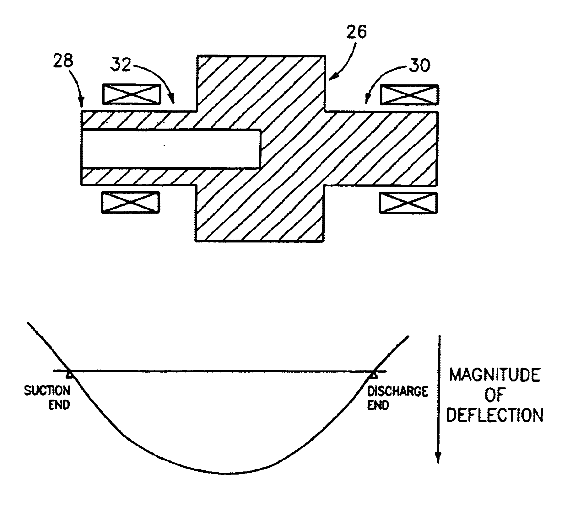
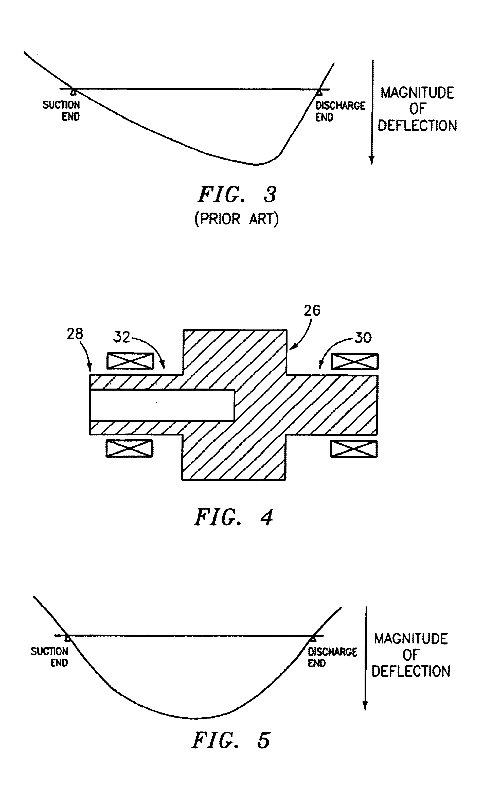
[0019]The invention relates to screw compressors and, more particularly, to modification of screw compressors for reducing variance in clearance between compressor components, especially in an expected operating envelope. In addition to reducing clearance variance, the designer may modify screw compressor design such that the compressor operates with smallest clearances at high pressure ratio operating conditions where effects of clearance on performance are the most important.

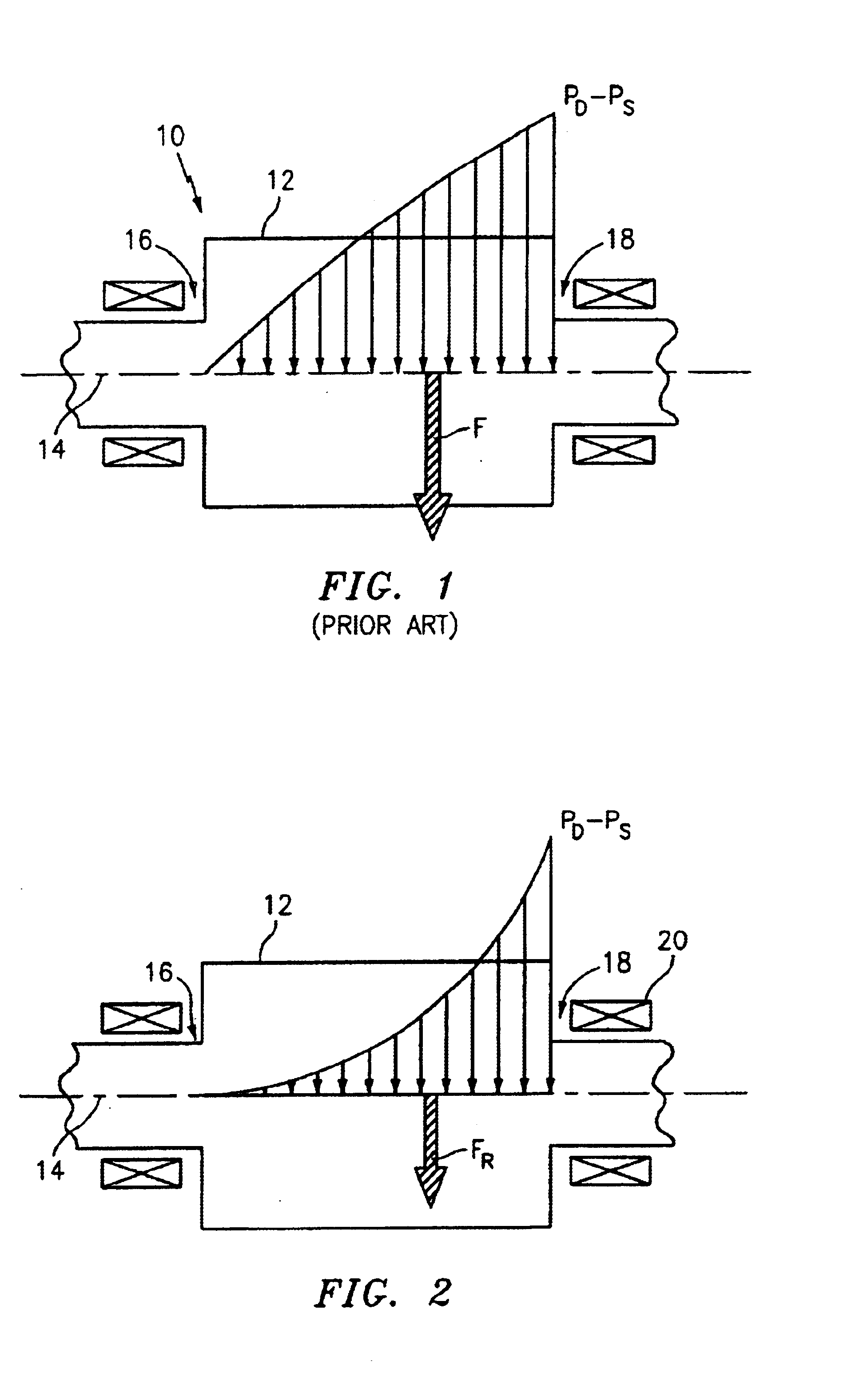
[0020]As is well known, screw compressors operate to compress refrigerant and involve screw rotors rotating within a housing and fed with refrigerant which is compressed as it travels along the length of the rotors. During operation, potentially large pressures and forces are generated and exerted against the rotor and housing of screw compressors, and thermal distortions are also experienced. Such pressure loading and thermal distortion result in undesirable flexing of components so as to provide for variatio...


PUM


Abstract

A screw compressor includes a housing and a screw rotor disposed in the housing and rotatable relative to the housing for compressing a refrigerant, the housing and the screw rotor having a rest condition, and an operating condition wherein at least one of the housing and the rotor deflect from the rest condition, and structure for at least one of reducing deflection from the rest condition and evenly distributing deflection from the rest condition when the rotor is in the operating condition, whereby clearance between the housing and the rotor is optimized in the operating condition.

Description

BACKGROUND OF THE INVENTION[0001]Screw compressors are widely used in refrigeration and other environments, and involve screw rotors rotated within a housing or casing to compress refrigerant to obtain the desired objectives. Excessive clearance between screw rotors and the housing results in loss of efficiency, while insufficient clearance results in rubbing and potential failures due to scoring or excessive wear of compressor components.[0002]Ideally, screw compressors would be provided having clearance of zero or as close to zero as possible along the entire rotor length, for all operating conditions of the compressor. Of course, it is impossible to achieve such zero clearance as different operating conditions subject the compressor to different stresses and forces which cause the clearance to vary across the rotor length.[0003]The primary object of the present invention is to modify screw compressor design to reduce clearance along the rotor length and / or reduce clearance variat...

Claims


Application Information

Patent Timeline
Patent Type & Authority Patents(United States)
IPC IPC(8): F04C18/08
CPCF04C18/084
Inventor LIFSON, ALEXANDERBUSH, JAMES WILLIAMDANIELS, MARKLIN, RENGROUSSEAU, WILLIAMWAGNER, TIMYANNOSCOLI, DONALD
Owner CARRIER CORP
Why Eureka
Try Eureka