Draw Forming Method and Device

a technology of drawing and forming method, applied in the field of drawing forming method and device, can solve the problem of marked non-uniform forming dimensions, and achieve the effect of reducing non-uniformity, reducing non-uniformity, and extremely small deflection in the central section of the blank material

Inactive Publication Date: 2008-05-01
HONDA MOTOR CO LTD
View PDF2 Cites 40 Cited by
  • Summary
  • Abstract
  • Description
  • Claims
  • Application Information

AI Technical Summary

Benefits of technology

[0012]In the thus-arranged device, the press operates the first holder means, the outer peripheral section of the blank material is restrained by the first holder means, and the press is then lowered further. The second holder means positioned on the inside of the first holder means then stretches the middle of the blank material outward. As a result, the deflection in the central section of the blank material is extremely small, and it is possible to reduce nonuniformities in the positional relationship between the central section and the upper and lower dies. It is therefore possible to reduce nonuniformities in the dimensions of the formed article when drawing is performed.
[0013]Preferably, in the device of the present invention, the press is a double-action press; the first restraining position is the position in which the first holder means protrudes past the second holder means and in which the blank material is held by the lowering of the double-action press; the second restraining position is the position in which the double-action press is lowered further from the first restraining position; the upper die is held to be capable of sliding in relation to the second holder means, and is disposed separate from an inner slider of the double-action press; and the first holder means and second holder means are fixed to an external slider positioned on the outside of the inner slider. As a result, tensile force is applied to the inside of the outer peripheral section and to the central section of the blank material until the blank material reaches the second restraining position while the outer peripheral section is restrained at the first restraining position, and deflection in the central section of the blank material can be prevented from occurring.

Problems solved by technology

As a result, there is concern that the forming dimensions will be markedly nonuniform.

Method used


Image

  • Draw Forming Method and Device
  • Draw Forming Method and Device
  • Draw Forming Method and Device

Examples


first embodiment

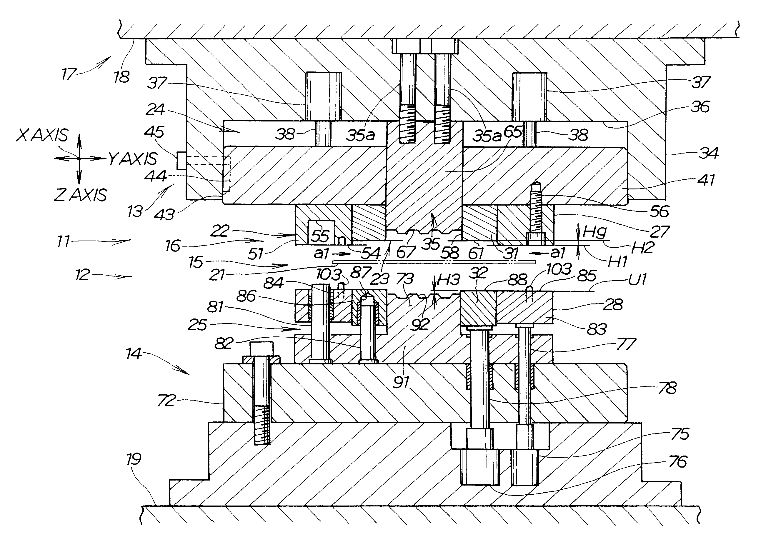
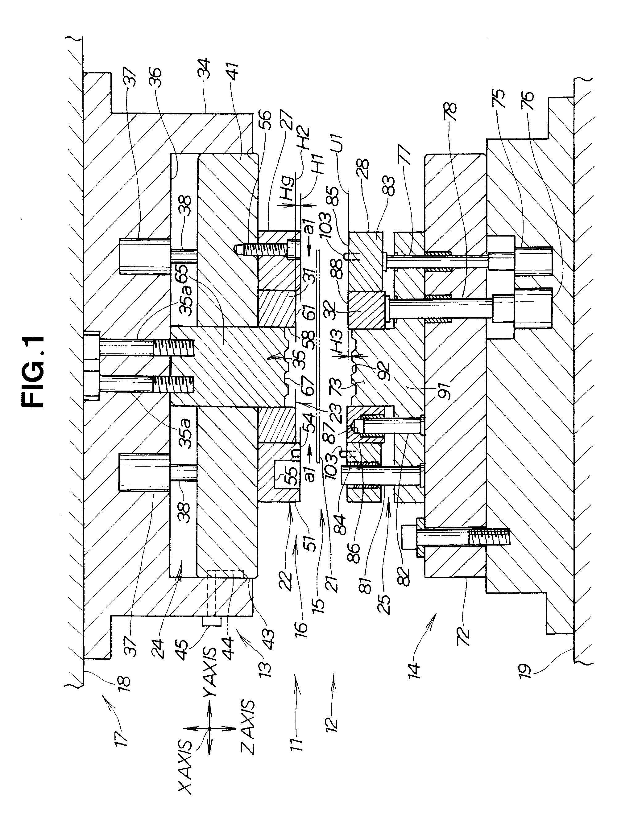
[0030]A draw forming device 11 of the first embodiment shown in FIG. 1 is composed of a metal die unit 12 comprising an upper metal die unit 13 and a lower metal die unit 14, and a blank holder 16 provided to the metal die unit 12 to apply pressure to the blank material 15. The upper metal die unit 13 is mounted on a ram 18 of a press 17. The lower metal die unit 14 is mounted on a bed 19 of the press 17. The draw forming device 11 performs draw forming.

[0031]The blank holder 16 includes first holder means 22 for restraining the outer peripheral section 21 (restraint region 98 in FIG. 3) of the blank material 15, and second holder means 23 disposed on the inside (in the direction of the arrows a1, a1) of the first holder means 22. An upper cushion mechanism 24 is mounted on the upper metal die unit 13, and a lower cushion mechanism 25 is mounted on the lower metal die unit 14 in order to operate the first and second holder means 22, 23.

[0032]The first holder means 22 is composed of ...

second embodiment

[0087]A draw forming device 211 of the second embodiment shown in FIG. 7 is composed of a metal die unit 212 comprising an upper metal die unit 213 and a lower metal die unit 214, and a blank holder 216 provided to the metal die unit 212 to hold down the blank material 15. The upper metal die unit 213 is mounted on the double-action press 217. The lower metal die unit 214 is mounted on a bed 219.

[0088]The double-action press 217 includes an inner slider 245 for applying pressing force in order to form the blank material 15, and an external slider 246 disposed on the outside of the inner slider 245 to hold down the blank material 15. The external slider 246 is raised and lowered individually by hydraulic pressure, for example.

[0089]The upper metal die unit 213 is composed of an upper base member 234 integrally mounted on the external slider 246 of the double-action press 217, and an upper die 235 disposed inside an open section 247 formed in the center of the upper base member 234.

[0...


PUM

PropertyMeasurementUnit
pressureaaaaaaaaaa
tensile forceaaaaaaaaaa
dimensionsaaaaaaaaaa

Abstract

A draw forming method for drawing a blank material (15). In this method, a restraint region (98) that is an outer peripheral section (21) of the blank material is held by a first holder means (22), and then a tension region (97) inside the outer peripheral section is displaced upward by a second holder means (23) relative to the restraint region. The displacement applies tensile force to a drawing region (96) that is the central section of the blank material.

Description

TECHNICAL FIELD[0001]The present invention relates to a draw forming method and device for reducing deflection created in the center of a blank material when the blank material is subjected to plastic working using a press and a metal die unit.BACKGROUND ART[0002]Japanese Utility Model Laid-Open Publication No. H01-153820, for example, proposes a draw forming method in which the periphery of a blank material is held by pressure from a blank holder, and the blank material is formed when subjected to plastic working using a metal die unit mounted on a press. This draw forming is described below with reference to FIGS. 13A through 13C hereof.[0003]In a forming method that uses a conventional drawing die 301, the periphery of a blank material B is first pressed by an upper die holddown 303 of an upper die 302 and a lower die holddown 305 of a lower die 304, and a section adjacent to the center of the blank material B is pressed by a pad 306 and a cushion 307, as shown in FIG. 13A.[0004]...

Claims


Application Information

Patent Timeline
Patent Type & Authority Applications(United States)
IPC IPC(8): B21D22/22
CPCB21D24/04B21D22/02
Inventor HORI, YUICHIKONNO, YUICHIMONDA, TAKANORIONO, HIROSHI
Owner HONDA MOTOR CO LTD
Why Eureka
Try Eureka