Cargo carrier

a carrier and cargo technology, applied in the field of cargo carriers, can solve the problems of increasing the number of carriers, mounting components, increasing the cost of storage space, and reducing the efficiency of transportation, so as to facilitate convenient or efficient carrier positioning, maximize aerodynamic flow, and save fuel consumption of the vehicle

Active Publication Date: 2019-08-20
WILLIAMS MARTY
View PDF24 Cites 8 Cited by
  • Summary
  • Abstract
  • Description
  • Claims
  • Application Information

AI Technical Summary

Benefits of technology

[0015]Adjustability of the arm members' length enables changing the height of the members relative to the mounting mechanism, as well as, changing the distance between the arm members. These angularly adjustable members thus impart versatile adaptability of the present cargo carrier to a wide variety of mounting mechanisms and combinations thereof as well as to applications hauling diverse sized and shaped cargo, which may include, without limitation, recreational, construction, landscaping and other equipment, tools and supplies.
[0018]The carrier according to the present invention is easily assembled and installed on a variety of surfaces including, without limitation, vehicle or trailer surfaces, bars and rails, hitch receivers, tow towers, spare tires mounted on rear exteriors, hatchbacks, rooftop or truck bed bars, or upper surfaces of truck beds, rails, or bus fronts.
[0022]The base plate preferably includes upwardly angled flanges extending from opposing sides of the base plate. In particularly preferred embodiments of the base plate according to the present invention, there is a drain hole between the upwardly angled flanges. Preferred embodiments of the present invention further include a base plate with holes, notches, pockets or protrusions for receiving and securing cargo fasteners. Preferred embodiments of the present invention further include bolt holes for attachment of a base plate to a surface, tube or rail on a vehicle or trailer. Alternatively, the base plate may be permanently secured to the surface, tube or rail by, for example, welding it thereon. With regard to hitch, trailer tower, tailgate, trunk or hatchback mounts, a further advantage is the present inventions ability to be partially disassembled to allow access into the rear of the vehicle without interfering with the vehicle tailgate.
[0026]Alternative embodiments of this invention facilitate convenient or efficient carrier positioning by deploying a tilt bracket pivotable to form varying angles along a vertical planar axis. As with the aforedescribed swivel base, embodiments employing rotational or pivoting tilt brackets enable facile fastening of cargo to the cargo carrier by providing a mechanism whereby a convenient proximal position for fastening and unfastening the cargo can be accessed, pivotal tilting back and forth provided by the latter mounting mechanism further enables orienting the cargo to maximize aerodynamic flow and thereby conserves fuel consumption of the vehicle.
[0027]Another aspect of the present invention is provided by alternative embodiments employing various types of fasteners adaptable to differing recreational equipment, tools and other cargo. Such fasteners and supports include, without limitation, cradles for wheels or other suitably shaped structures, hooks, bungees, clamps, clips, clasps and elastomer cords. Fasteners and supports are pinned, looped, clamped or otherwise secured on the cargo carrier to accommodate differing sizes and shapes of the recreational equipment, tools and cargo cases. Adjustment of fasteners and supports along the angular orientation of arm members facilitate versatile adaptation accommodation to differing types, sizes and shapes of cargo.
[0029]Another feature of a preferred embodiment of the present invention enables adjustment of the height of the arm members and adapting fasteners to enable the cargo on rear of vehicle applications to be mounted well away from the heat of the vehicle tailpipe emission.

Problems solved by technology

The base plate on which such conventional carrier systems are permanently or semi-permanently mounted on the surface, bar or rail to which they correspond, and include securing mechanisms corresponding to a particular piece of equipment, case, or article, and lack adaptability to other types of surfaces or cargo.
These prior art carriers are heavy, and awkward to align and mount onto the vehicle.
Also, these carriers are often not adaptable to alternative applications and thus require different carriers for different cargo types, or even of different cycle species, such as unicycles, road bicycles and mountain bicycles.
A further disadvantage of such dedicated systems nature is the consequent increased number of carriers, mounting components and the attendant expense and storage space.
A particular problem with hitch mounted carriers is the use of the vehicle hitch receiver.
In that event, such a conventional hitch-mounted carrier cannot be mounted.
Other drawbacks of conventional carriers remain, however, many of which derive from their dedicated designs, which are typically adapted to particular vehicle surface and cargo types.
As a result, conventional carrier components for trunk or hatchback mounted systems typically cannot be used on roof top, truck bed, bus front, or surface mounted applications.
That is, mounting mechanisms and bars for use with framed carriers for trunks and hatchbacks primarily used for cars and other low profile vehicles cannot be interchanged with hitch or tow tower mounted systems popular for SUVs and trucks.
Thus, there is a lack of crossover applications for mounting mechanisms and cargo carrier systems enabling portability between vehicles, as well as, rooftop, trunk, and hatchback carriers, hitch-mounted, truck mounted trailer mounted and other carriers.
Moreover, conventional cargo carriers lack versatility with regard to cargo.
Similarly, cases and containers employ locks and clips limited to mounting systems typically located on vehicle rooftops.
In addition, conventional carrier systems typically employ fixed frames, which cannot be lengthened or angled, and are often molded or otherwise rigidly aligned to specific cargo configurations.
Such bicycle carrier frames thus typically are not adaptable to different bicycle or other cycle styles.
In addition, conventional carriers are heavy and awkward to align and mount onto the vehicle.
Many drawbacks result from such lack of versatility and portability, including limited or singular application cargo support bars and mounting mechanisms, of prior art cargo carriers.
Moreover these mounting devices are limited to specifically corresponding surfaces, tubes or rails; such conventional carriers thus lack portability.
Due to their lack of versatility and portability, conventional carriers require multiple and distinct mounts and brackets with limited or a single application suited to particular surfaces, rails or bars, depending on the size and shape of the equipment or other cargo.
Due to their lack of versatility and portability, conventional carriers required multiple and distinct mounts and brackets with limited or a single application suited to particular surfaces, rails or bars, depending on the size and shape of the equipment or other cargo.
The multiple and permanent mounting devices added to the disadvantages of such inflexible and non-portable prior art the further drawback of detracting from the aesthetic look of a vehicle and adding weight and aerodynamic obstruction increasing fuel cost.
In sum, there exists nothing in the prior art that provides a lightweight, versatile, readily adjustable and portable carrier adaptable to various vehicles, surfaces, bars and rails or shanks on which carriers are mounted.
There is also a lack of mounting mechanisms adaptable to various types, sizes and shapes of cargo, such as, for example, recreational, construction or yard equipment and tools cases between locations.

Method used


Image

  • Cargo carrier
  • Cargo carrier
  • Cargo carrier

Examples


Embodiment Construction

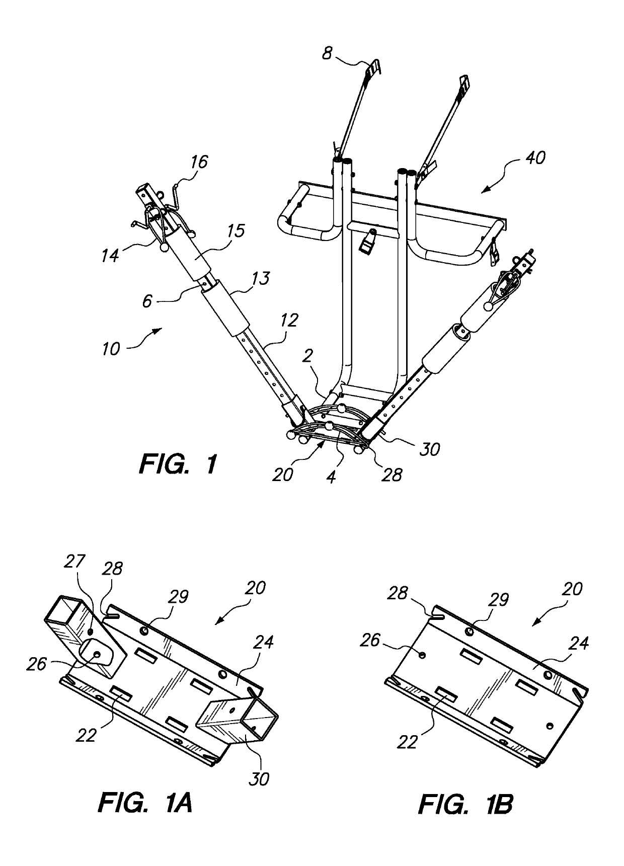
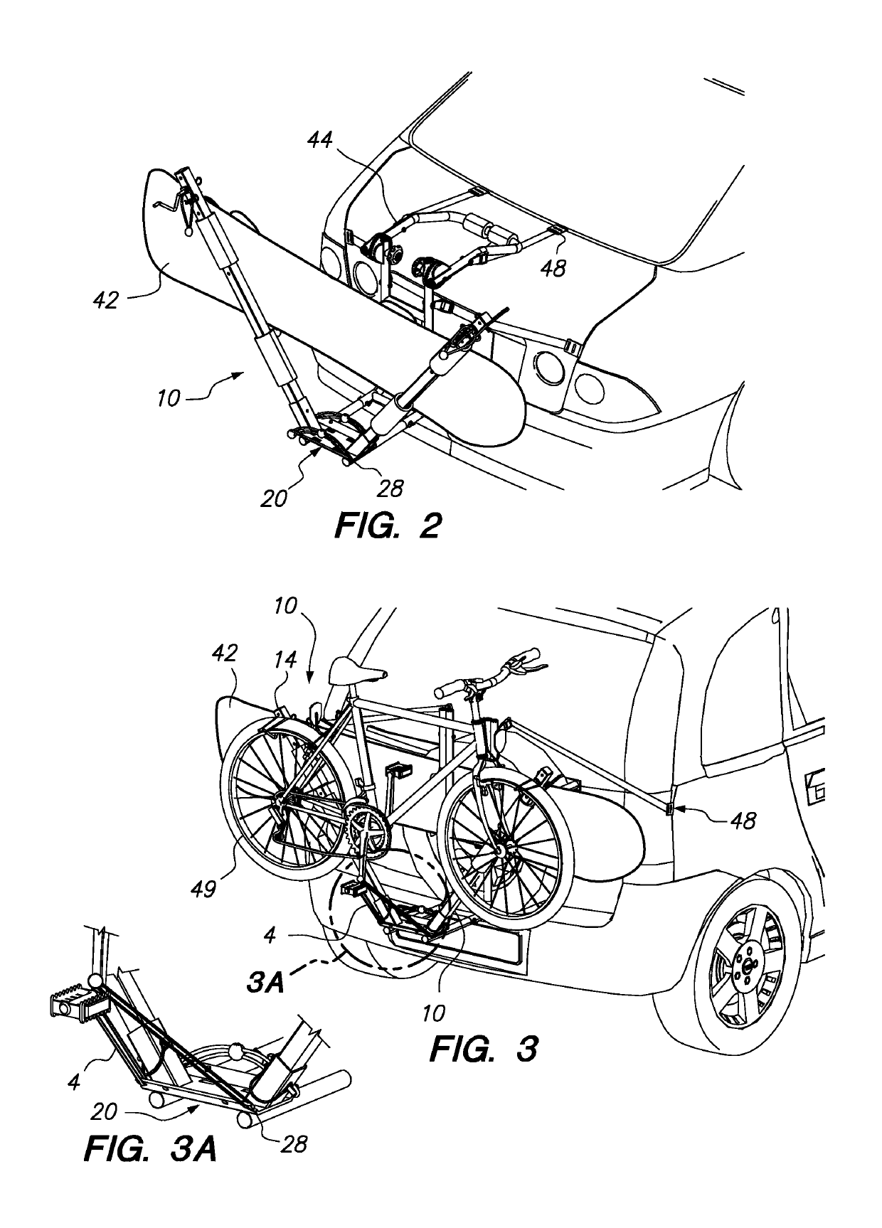
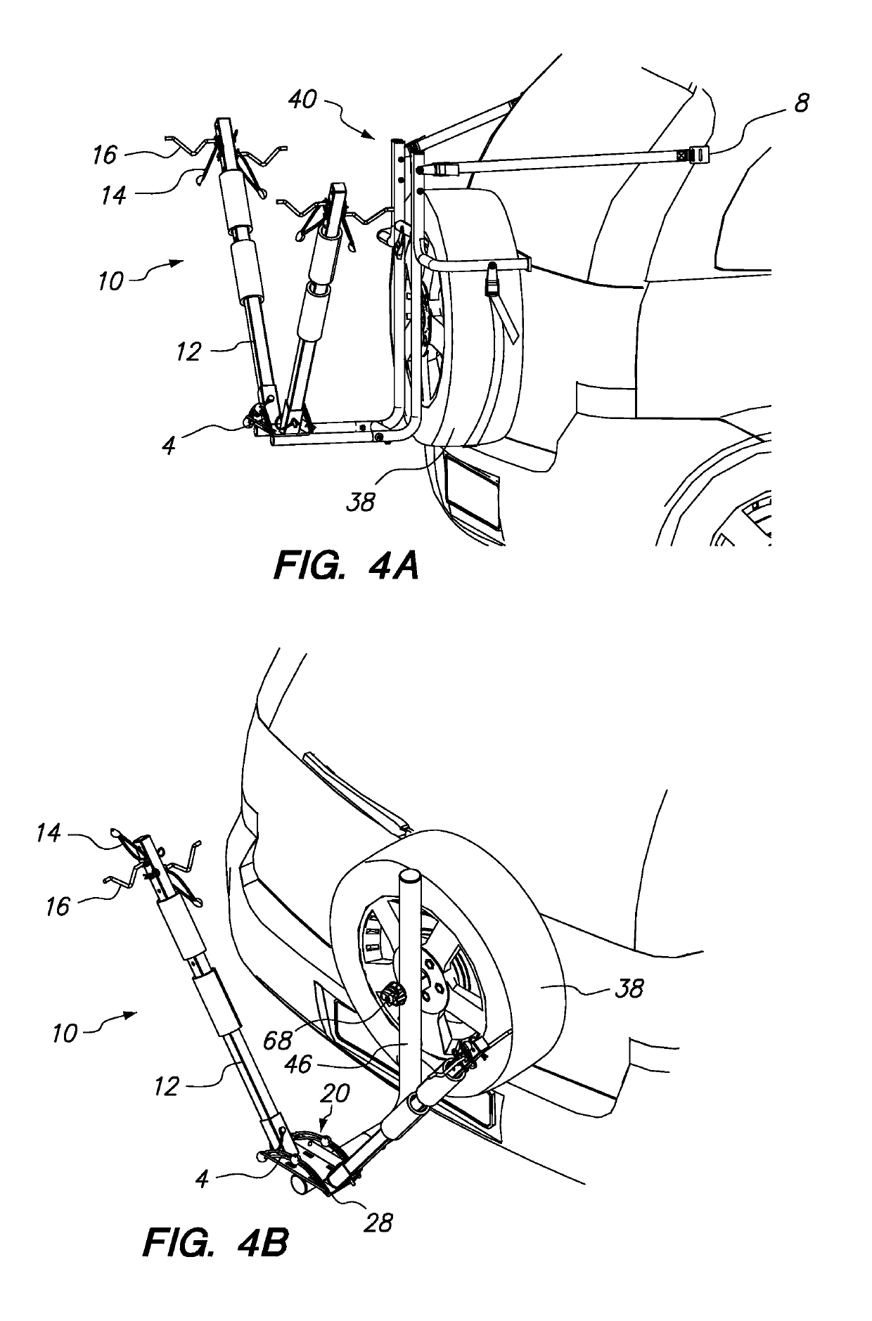
[0080]The present invention provides a cargo carrier 10 for mounting to a vehicle and carrying a range of equipment and other cargo, which may include, without limitation, recreational equipment such as cycles, skis, snowboards, surfboards, paddle boards, construction or landscaping equipment, or cases, bags or boxes holding smaller items. It is to be expressly understood that these exemplary embodiments are provided for descriptive purposes only and are not meant to unduly limit the scope of the present inventive concept. Preferred and alternative embodiments depicted in the drawings are illustrative of the numerous features of the present cargo carrier, including, without limitation, its versatile mounting mechanisms and cargo applications. Other embodiments of the cargo carriers and methods of use of the present invention are considered within the present inventive concept as set forth in the claims herein. For explanatory purposes only, the cargo carriers of the preferred embodi...


PUM


Abstract

A versatile and portable cargo carrier having angularly adjustable members adaptable to various uses and cargo, including recreational, construction, landscaping and other equipment, tools and supplies of diverse sizes and shapes, comprising a base plate and mounting member attachable to a corresponding surface on a vehicle from which two adjustably angled arm members extend outwardly at an angle from the mounting member, a pivoting mechanism for adjusting the angle between the two arm members and one or more cargo fasteners employing fastening mechanisms suitable for corresponding equipment or cargo, and may include a mounting bar. This easily assembled and installed cargo carrier further provides a frame for attachment about a hitch, spare tire, hatchback, and includes mounting members including a base plate, hat bracket, rotational swivel or pivoting tilt base which can be combined with the two angular members enabling facile loading and fastening of cargo.

Description

CROSS REFERENCE TO RELATED APPLICATION[0001]This continuation in part application claims the benefit of U.S. patent application Ser. No. 11 / 697,294, filed on Apr. 5, 2007, which is incorporated herein by reference.FIELD OF THE INVENTION[0002]This invention relates to the field of cargo carriers.BACKGROUND OF THE INVENTION[0003]There exist numerous bicycle and other cargo carriers that mount to a vehicle or a trailer for transporting cargo from one location to another location. Conventional carriers have mounts adapted to particular roof-tops, trunks, trailers and hitches for a particular vehicle surface or accessory rail, tube or bar and to carry a particular item. Hitch-mounted carriers are popular with SUVs and other vehicles that have hitch or tow tower attachments. Similarly, truck bed carriers are uniquely configured for use in truck beds. The base plate on which such conventional carrier systems are permanently or semi-permanently mounted on the surface, bar or rail to which t...

Claims


Application Information

Patent Timeline
Patent Type & Authority Patents(United States)
IPC IPC(8): B60R9/00B60R9/06B60R9/10
CPCB60R9/06B60R9/10Y10S224/924
Inventor WILLIAMS, MARTY
Owner WILLIAMS MARTY
Why Eureka
Try Eureka