Deformation compensating device

A deformation compensation and dynamic template technology, applied in the field of deformation compensation devices, can solve the problems of inconvenient installation and assembly, complex structure, etc., and achieve the effect of simple structure, good stability, and convenient installation and assembly

Active Publication Date: 2013-12-11
SUZHOU CHENGSHI CASTING
View PDF5 Cites 7 Cited by
  • Summary
  • Abstract
  • Description
  • Claims
  • Application Information

AI Technical Summary

Problems solved by technology

[0004] Therefore, the technical problem to be solved by the present invention lies in the complex structure and inconvenient installation and assembly of the elastic compensation element on the

Method used


Image

  • Deformation compensating device
  • Deformation compensating device
  • Deformation compensating device

Examples


Embodiment Construction

[0022] In the following, the present invention will be further described by using the following embodiments in conjunction with the accompanying drawings.

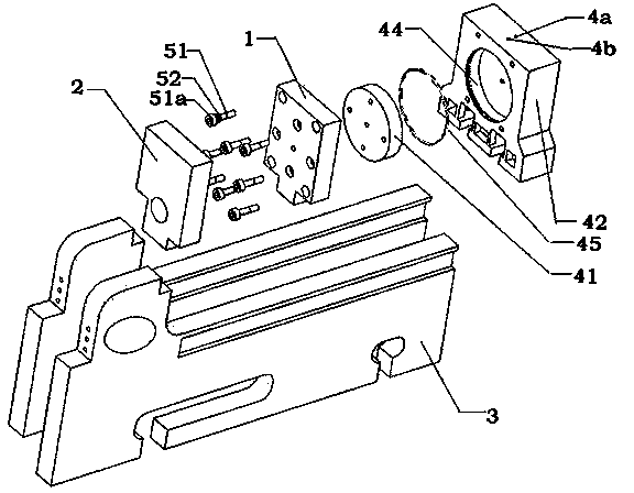
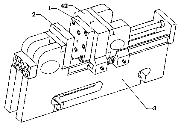
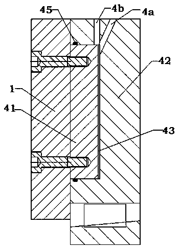
[0023] Such as Figure 1-4 Shown is the deformation compensation device of the present invention, which is arranged between the movable template 1 and the pushing mechanism, and / or between the fixed template 2 and the frame 3, including: fixed with the movable template 1 or the fixed template 2 The connected slider 41 and the support 42 fixedly connected with the pushing mechanism or the frame 1, the slider 41 is slidably connected to the support 42 and forms a circle with the support 42 A sealed chamber 43, which communicates with pressurized liquid or pressurized gas. In this embodiment, the deformation compensating device is arranged between the moving template 1 and the pushing mechanism, the slider 41 is fixedly connected to the moving template 1, and the support 42 is fixed to the pushing mechanism. connect.

[00...


PUM


Abstract

The invention provides a deformation compensating device which is arranged between a moving template and a pushing mechanism and/or between a fixed template and a framework. The deformation compensating device comprises a sliding block fixedly connected with the moving template or the fixed template, and a supporting seat which is fixedly connected with a pushing mechanism or the framework, wherein the sliding block is connected with the supporting seat in a sliding manner, the sliding block and the supporting seat can form a sealing cavity, and the sealing cavity is communicated with pressure fluid or pressure gas. The deformation compensating device provided by the invention has the advantages that deformation generated when a movable die and a fixed die are subjected to die compounding is compensated, the deformation compensating device plays the deformation compensation role, the structure is simple, the processing is easy, the installation and the assembly are convenient, and the deformation compensating device is widely applied to minitype die casting machine or an injection molding machine being less than 280T.

Description

technical field [0001] The invention relates to a deformation compensation device, which belongs to the technical field of injection molding or die-casting. Background technique [0002] When die-casting or injection molding a mold, the molten material is usually poured into the cavity and then hardened into shape. During the pouring process, a certain pressure needs to be applied to make the material fill the entire cavity. However, in the cavity with a specific shape formed by fastening the movable mold and the fixed mold, the stress on each point of the inner wall is not uniform during the mold filling process after the mold is locked, which causes the dynamic mold and the fixed mold to have problems. A certain degree of deformation, and then the shape of the cavity also changes, affecting the final molded product. Therefore, in order to improve the yield of products, it is necessary to set up a deformation compensation device to compensate for the above deformation. ...

Claims


Application Information

Patent Timeline
IPC IPC(8): B29C45/58B22D17/20
Inventor 捷卡姆·查马特
Owner SUZHOU CHENGSHI CASTING
Why Eureka
Try Eureka