Anchoring rail for anchoring in concrete

a technology for anchoring rails and concrete, which is applied in the direction of threaded fasteners, girders, mechanical devices, etc., can solve the problems of concrete cracks, and the material failure of the anchoring rail itsel

Active Publication Date: 2019-08-20
LEVIAT GMBH
View PDF108 Cites 6 Cited by
  • Summary
  • Abstract
  • Description
  • Claims
  • Application Information

AI Technical Summary

Benefits of technology

[0004]It is an object of the invention to provide an anchoring rail which, when embedded in concrete, is highly stable in relation to the loading by forces acting thereon.

Problems solved by technology

In the process, cracks may arise in the concrete.
In addition to a possible failure of the fastening of the anchoring rail in the concrete, a failure of the material of the anchoring rail itself is the greatest source of uncertainty for an anchoring rail based fastening system.
This may lead to deformation of the anchoring rail, wherein the region of the connection of anchor and base is typically secured by the anchor secured in the concrete and the regions of the base that are further away from the connecting point are bent in a direction away from the anchor.
In a following step, the base may tear out at the connecting point between base and anchor, whereupon the stability of the entire anchoring rail and the fastening thereof is impaired.
This also greatly impairs the stability of the anchoring rail.

Method used


Image

  • Anchoring rail for anchoring in concrete
  • Anchoring rail for anchoring in concrete
  • Anchoring rail for anchoring in concrete

Examples


Embodiment Construction

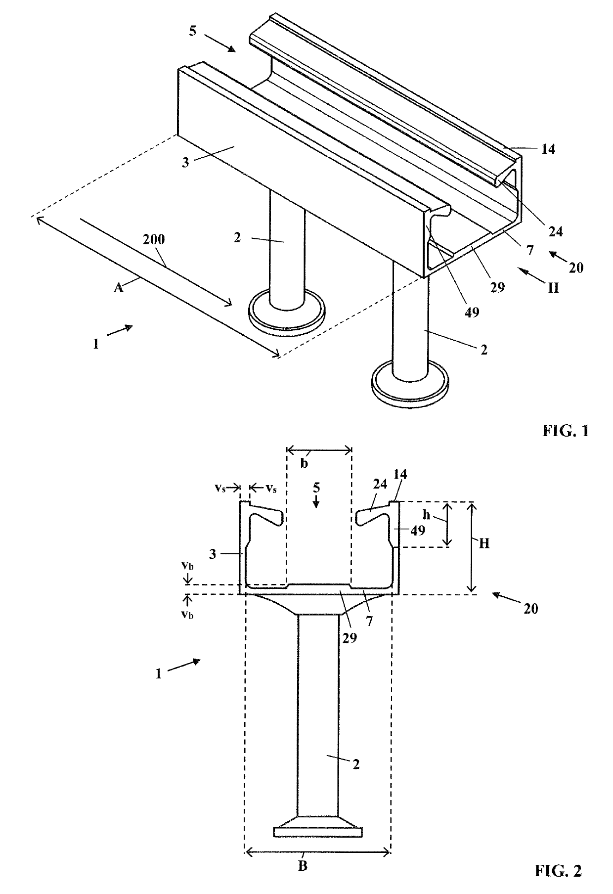
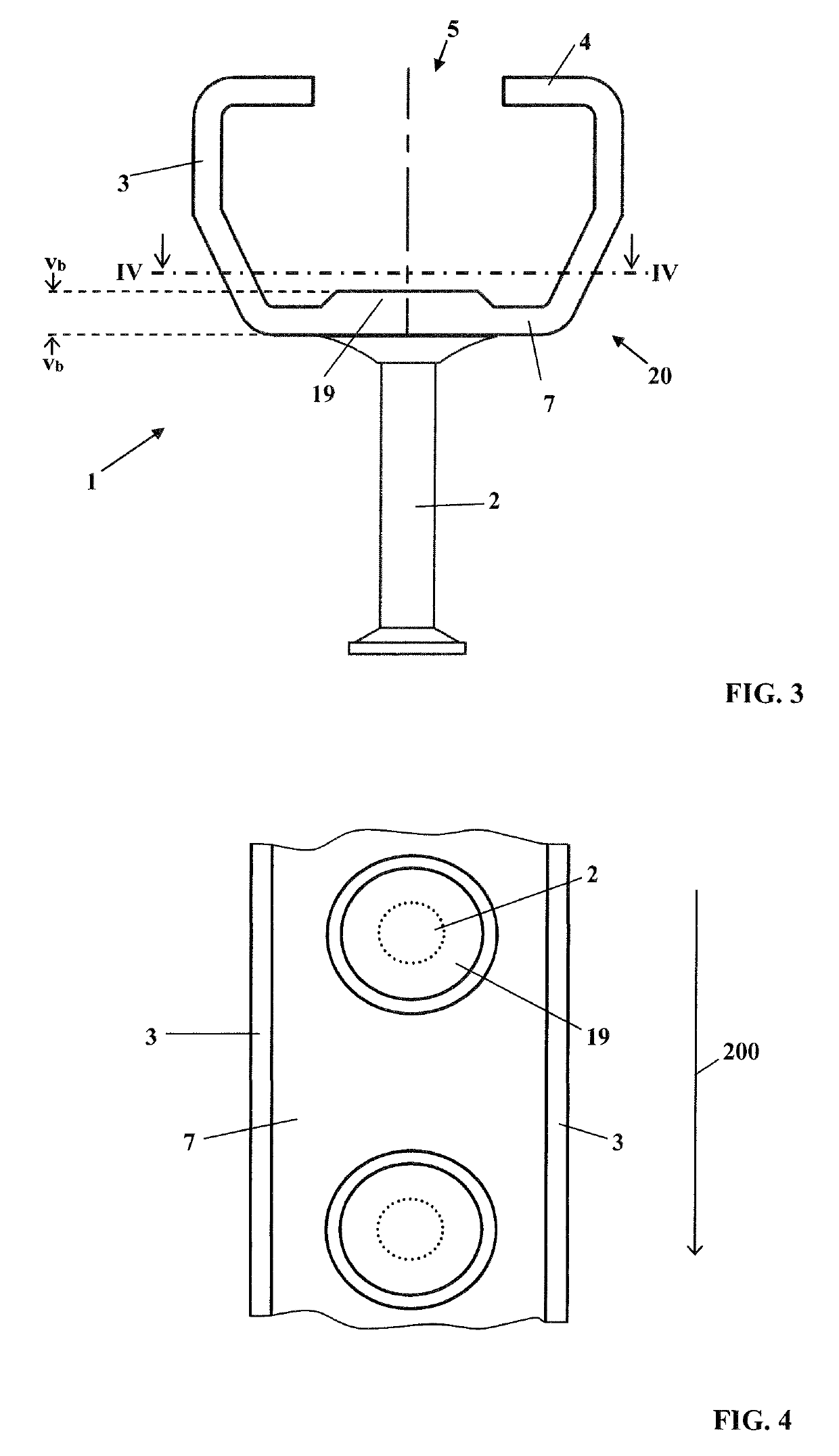
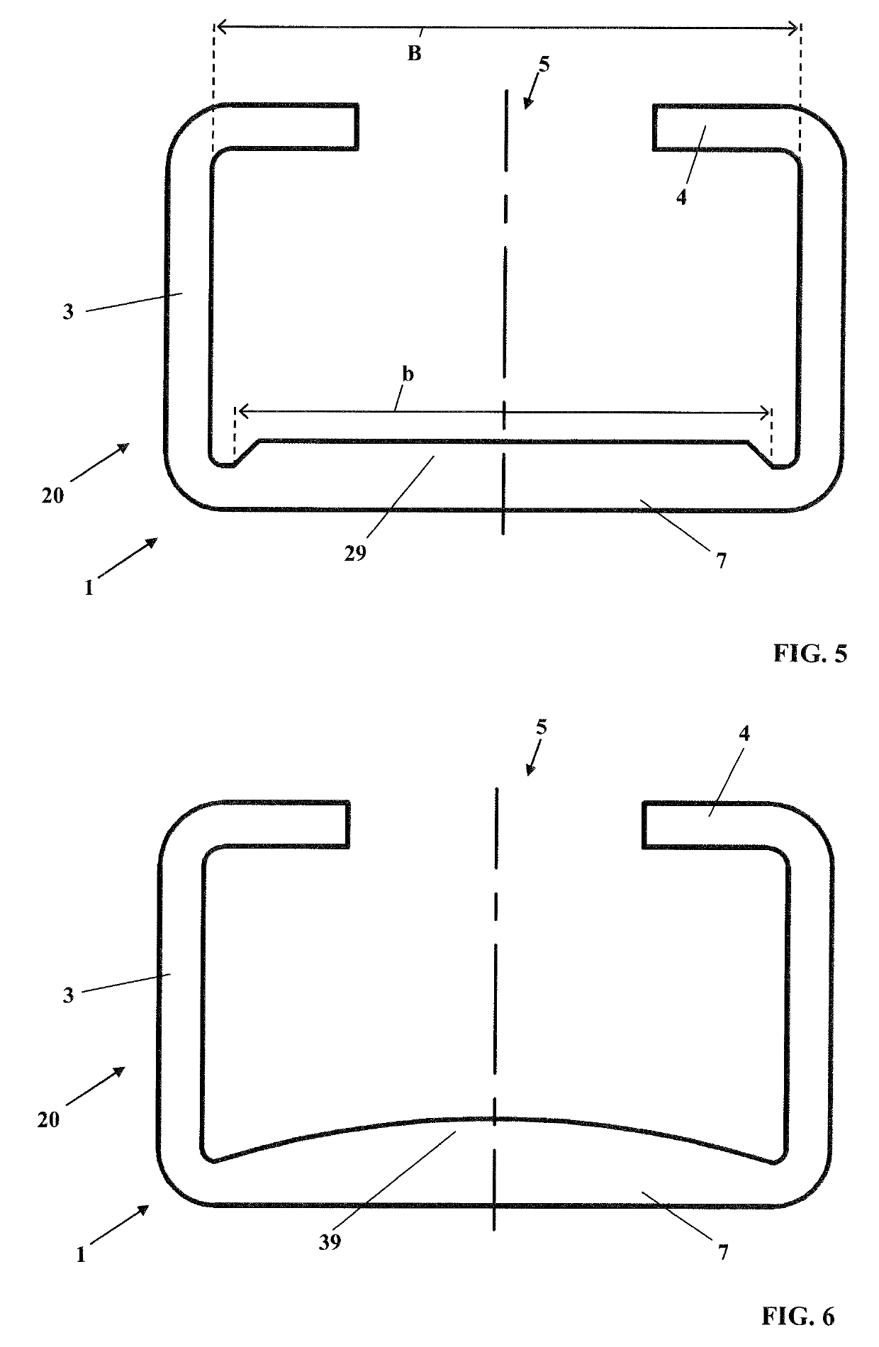
[0038]FIG. 1 shows the perspective view of an anchoring rail 1. Such anchoring rails are cast, for example, into concrete. The anchoring rail 1 has a substantially C-shaped cross section. Anchors 2 are provided for anchoring the anchoring rail 1 in the concrete. The anchors 2 are arranged orthogonally to a flat base 7. The anchors 2 are arranged in the center of the base 7 with respect to the direction transverse to the longitudinal direction 200 of the anchoring rail 1. Side walls 3 are arranged orthogonally to the base 7. The two side walls 3 run parallel to each other. The side walls 3 together with the base 7 form a base body 20 of the anchoring rail 1. The side walls 3 together with the base 7 form outer edges of the base body 20 of the anchoring rail 1. The base body 20 has a substantially U-shaped cross section. Free limbs 24 are arranged at the same height at that region of the side walls 3 which faces away from the base 7. The side walls 3 protrude over the free limbs 24. I...


PUM


Abstract

The invention relates to an anchoring rail with a substantially C-shaped cross section for anchoring in concrete. The anchoring rail includes a cross sectionally substantially U-shaped base body, two free limbs and at least one anchor. The base body includes a base and two side walls. The two free limbs are arranged opposite the base of the base body. The at least one anchor is arranged on the base. Between the free limbs, a slot is formed in the longitudinal direction of the anchoring rail. The anchoring rail has at least one thickened portion on the base body.

Description

CROSS REFERENCE TO RELATED APPLICATION[0001]This application claims priority of European patent application no. 15001146.8, filed Apr. 18, 2015, the entire content of which is incorporated herein by reference.BACKGROUND OF THE INVENTION[0002]An anchoring rail of the type in question is known from EP 2 478 163 B1. Anchoring rails of this type are cast into concrete in order then to be able to fasten objects thereon with the aid of rail nuts, engage behind parts, head screws or hammer head screws. Together with such fastening elements, the anchoring rail forms a fastening system. The weight of the fastened objects is transmitted via the rail geometry and the anchor of the anchoring rail into the concrete. In the process, cracks may arise in the concrete. For the controlled formation of cracks, crack initiator means are provided on the anchoring rail in EP 2 478 163 B1.[0003]In addition to a possible failure of the fastening of the anchoring rail in the concrete, a failure of the mater...

Claims


Application Information

Patent Timeline
Patent Type & Authority Patents(United States)
IPC IPC(8): E04B1/41E04C3/04F16B37/04
CPCE04B1/4107F16B37/047E04C2003/0473
Inventor ALBARTUS, DIRKHAEUSLER, FRANKBORGSTEDE, DIRKHANKE, ANDREAS
Owner LEVIAT GMBH
Why Eureka
Try Eureka