Flying disk with airfoils

a technology of flying disks and airframes, applied in the field of flying disks, can solve problems such as stalls, and achieve the effects of enhancing the overall flight characteristics of the device, reducing the stalling rate, and increasing the li

Active Publication Date: 2019-09-03
FISHER MYLES A
View PDF9 Cites 2 Cited by
  • Summary
  • Abstract
  • Description
  • Claims
  • Application Information

AI Technical Summary

Benefits of technology

[0010]The flying disk with airfoils of the present invention addresses the aforementioned desires in the art by combining the features of a standard flying disk with the features of a boomerang so as to enhance the overall flight characteristics of the device when compared to either the flying disk or the boomerang alone. This combination results in a device that uses two different airfoil systems combined with two different gyroscope systems. The result is a flying disk with greater lift and greater angular rotation so that greater lineal distances and greater airtime and better return flight path characteristics can be achieved relative to either a flying disk or a boomerang alone.

Problems solved by technology

This pressure differential results in lift as the higher pressure on the underside of the airfoil pushes the airfoil toward the lower pressure on the top side of the airfoil.
The downwardly depending rim of the flying disk creates considerable drag for the flying disk in flight, however, the thick rim increases the disk flight stability by increasing the moment of inertia and its associated gyroscopic precession.
As the flight of a boomerang progresses, the rotational velocity of the boomerang slows, and on the return flight path the boomerang spins more slowly, slowing to an almost hover and then falls to the ground as the loss of linear velocity causes drag to exceed lift and loss of moment of inertia causes instability in flight, so that gravity takes over and the boomerang stalls.

Method used


Image

  • Flying disk with airfoils
  • Flying disk with airfoils
  • Flying disk with airfoils

Examples


Embodiment Construction

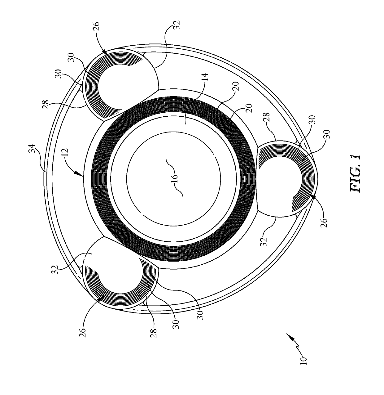
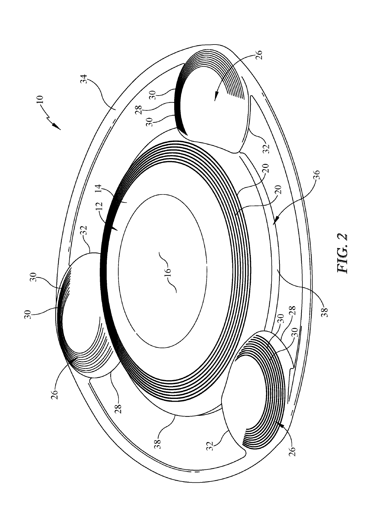
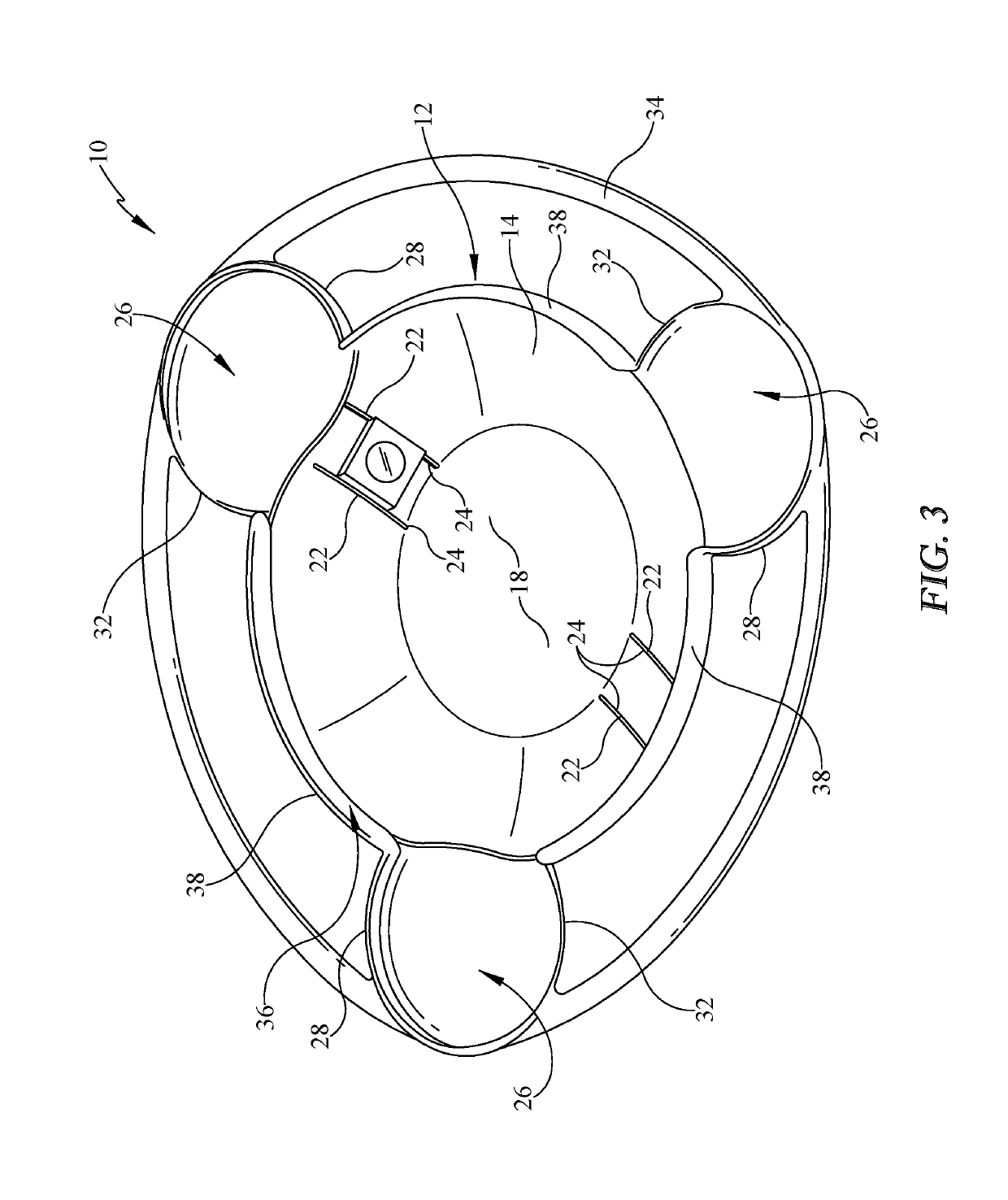
[0022]Referring now to the drawings, it is seen that the flying disk with airfoils of the present invention, generally denoted by reference numeral 10, is comprised of a disk member 12 that has a circular body member 14 with an upper surface 16 and a lower surface 18 forming a top closed dome. One or more circular ridges 20 may be located on the upper surface 16 in order to act a turbulators as is well known in the art of flying disks.

[0023]One or more pairs of rails 22 may extend along a portion of the lower surface 18, the rails 22 being located equidistant on opposing sides of a midline passing through the disk member 12. Each rail 22 has a channel 24 such that optional features can be supported within the channels 24, which optional features may include a weight to change the flight dynamics of the flying disk with airfoils 10, an air driven insert whistle or warbler that whistles while the disk member 12 is in flight with an air intake orifice located on the rim 12, a battery t...


PUM


Abstract

An aerodynamic flying device combines features of a flying disk and a boomerang. The device uses a closed dome flying disk with one or more cambered wings attached to the disk. The wings have their leading edges facing in the direction of rotation of the disk. The wings may be asymmetrically cambered or may be symmetrically cambered about the center line of each wing. An outer ring is attached to the outer edges of each wing. A downwardly dependent curved rim runs along the outer periphery of the device with a discontinuity of the rim occurring along the joinder line whereat each wing attaches to the disk. Another discontinuity of the rim may occur along a portion of the trailing edge of each wing.

Description

BACKGROUND OF THE INVENTION1. Field of the Invention[0001]The present invention relates to a flying disk that has one or more airfoils attachable thereto, either fixedly or removably, in order to enhance the flight characteristics of the disk, the invention having characteristics of both a flying disk and a boomerang.2. Background of the Prior Art[0002]The flying disk is a disk-shaped gliding object that has a closed dome curving to a downwardly depending circumferential rim and is used for throwing and catching by recreationalists the world over. Walter Fredrick Morrison developed a disk which he called the Pluto Platter and which became a huge commercial success. The Pluto Platter is considered the archetype for all modern flying disks. Morrison, who was awarded design patent D183,626 in 1964 for the Pluto Platter, sold the Pluto Platter to Wham-O Holding, Ltd., of Kowloon, Hong Kong, the prior year. Wham-O's general manager and vice president for marketing, Edward Headrick, redes...

Claims


Application Information

Patent Timeline
Patent Type & Authority Patents(United States)
IPC IPC(8): A63H33/18A63B65/00
CPCA63H33/18
Inventor FISHER, MYLES A
Owner FISHER MYLES A
Why Eureka
Try Eureka