Magnetic recording medium

a recording medium and magnetic recording technology, applied in the field can solve the problems of deterioration of read-write characteristics of magnetic recording mediums, decrease in thermal stability of recorded magnetization, etc., and achieve the effect of reducing the surface roughness of the magnetic recording layer and squareness ratio mr/ms

Active Publication Date: 2019-04-30
FUJI ELECTRIC CO LTD
View PDF13 Cites 2 Cited by
  • Summary
  • Abstract
  • Description
  • Claims
  • Application Information

AI Technical Summary

Benefits of technology

[0012]Some of constitutional examples of the present invention aim to provide a magnetic recording medium in which the surface roughness of the magnetic recording layer can be reduced without adversely affecting the magnetic properties of the magnetic recording layer, such as the magnetic anisotropy constant Ku, the saturated magnetization Ms, and the squareness ratio Mr / Ms.
[0014]By adopting the above-described configuration, it becomes possible to obtain a magnetic recording medium having the seed layer having a small surface roughness, and the magnetic recording layer having a small surface roughness. Thus, the obtained magnetic recording medium contributes to excellent flying characteristics of the magnetic head.

Problems solved by technology

On the other hand, the reduction in the grain diameter of the magnetic crystal grains leads to a decrease in thermal stability of the recorded magnetization (also referred to as signals).
If the surface roughness of the magnetic recording medium increases, the read-write characteristics of the magnetic recording medium may be deteriorated by undesirable influence of the surface roughness upon flying characteristics of the magnetic head.

Method used


Image

  • Magnetic recording medium
  • Magnetic recording medium
  • Magnetic recording medium

Examples


example 1

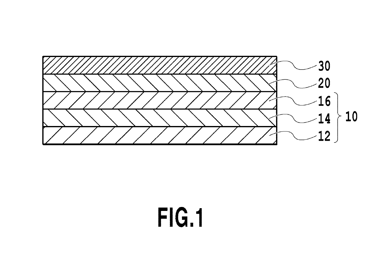
[0039]A chemically strengthened glass substrate having a flat surface (N-10 glass substrate manufactured by HOYA CORPORATION) was washed to prepare non-magnetic support 12. The washed non-magnetic support 12 was brought into a sputtering device. Then, Ta adhesive layer 14 having a thickness of 5 nm was formed by an RF magnetron sputtering method in Ar gas at a pressure of 0.20 Pa which uses a Ta target placed 180 mm apart from the substrate. The electric power applied to the target was 200 W.

[0040]Then, Cr interlayer 16 having a thickness of 20 nm was formed by an RF magnetron sputtering method in Ar gas at a pressure of 0.20 Pa which uses a Cr target placed 180 mm apart from the substrate, to obtain substrate 10. The electric power applied to the target was 600 W.

[0041]Then, to the substrate 10 was formed MnCr2O4 seed layer 20 having a thickness of 10 nm by an RF magnetron sputtering method in Ar gas at a pressure of 0.18 Pa which uses an MnCr2O4 target placed 240 mm apart from the...

example 2

[0052]The substrate 10 was obtained by forming the Ta adhesive layer 14 having a thickness of 5 nm and the Cr interlayer 16 having a thickness of 20 nm onto the non-magnetic support 12, by means of the similar procedure to Example 1.

[0053]Then, to the substrate 10 was formed MnCr2O4 seed layer 20 having a thickness of 10 nm by an RF magnetron sputtering method in Ar gas at a pressure of 0.1 Pa which uses an MnCr2O4 target placed 166 mm apart from the substrate 10. The electric power applied to the target was 200 W. Further, the temperature of the substrate 10 was set to 430° C.

[0054]Then, the stacked body in which the seed layer 20 had been formed was heated to a temperature of 430° C., and FePt—C magnetic recording layer 30 having a thickness of 2 nm was formed by an RF magnetron sputtering method in Ar gas at a pressure of 1.5 Pa which uses an Fe50Pt50—C target placed 166 mm apart from the substrate 10. The content of C in the target was 40% by volume.

[0055]Further, the protective...

example 3

[0060]A magnetic recording media were obtained by repeating the procedure of Example 1, except that the substrate temperature was fixed to 350° C. and the thickness of the seed layer 20 was changed, during formation of the seed layer 20. The thickness of the seed layer 20 and the measurement result of the magnetic anisotropy constant Ku of the resultant magnetic recording media are shown in Table 3.

[0061]

TABLE 3EFFECT OF THICKNESS OF SEED LAYERThickness ofMagnetic AnisotropySeed LayerConstant Ku*1(nm)(×107 erg / cm3)20.36451.78103.09*1107 erg / cm3 = 1 J / cm3

[0062]As apparent from Table 3, the magnetic recording media having the large magnetic anisotropy constant Ku were obtained by setting the thickness of the seed layer to 5 nm or more.


PUM

PropertyMeasurementUnit
roughnessaaaaaaaaaa
thicknessaaaaaaaaaa
thicknessaaaaaaaaaa

Abstract

The purpose of the invention is to provide a magnetic recording medium in which the surface roughness of the magnetic recording layer can be reduced without deterioration of the magnetic properties of the magnetic recording layer. The magnetic recording medium of the present invention includes a substrate, a seed layer on the substrate, and a magnetic recording layer on the seed layer, wherein the seed layer contains Mn, Cr, and O, and has a spinel structure.

Description

CROSS-REFERENCES TO RELATED APPLICATIONS[0001]This application is a continuation application of PCT Application No. PCT / JP2015 / 005340 under 37 Code of Federal Regulations § 1.53 (b) and the said PCT application claims the benefit of Japanese Patent Application No. 2014-219203, filed Oct. 28, 2014, which is hereby incorporated by reference wherein in its entirety.BACKGROUND OF THE INVENTION[0002]Field of the Invention[0003]Some of constitutional examples of the present invention relate to a magnetic recording medium. In particular, some of constitutional examples of the present invention relate to a magnetic recording medium used in a hard disc magnetic recording device (HDD).[0004]Description of the Related Art[0005]Perpendicular magnetic recording system is adopted as a technique for increasing the magnetic recording density. A perpendicular magnetic recording medium at least comprises a non-magnetic substrate and a magnetic recording layer formed of a hard-magnetic material. Optio...

Claims


Application Information

Patent Timeline
Patent Type & Authority Patents(United States)
IPC IPC(8): G11B5/66G11B5/65G11B5/73
CPCG11B5/732G11B5/65G11B5/7379
Inventor MORIYA, TOMOHIRONAKATA, HITOSHIKATAOKA, HIROYASUKIKUCHI, HIROTOFURUTA, AKIRASHIMATSU, TAKEHITO
Owner FUJI ELECTRIC CO LTD
Why Eureka
Try Eureka