Supercharge Your Innovation With Domain-Expert AI Agents!

Wheel skirt shielding upper tire sidewall

a technology of upper tire sidewall and wheel skirt, which is applied in the direction of road transportation emission reduction, vehicle body streamlining, vehicle components, etc., can solve the problems of reducing propulsive efficiency, energy loss, and frictional drag force not uniformly distributed, so as to reduce vehicle drag, and increase vehicle propulsive efficiency

Active Publication Date: 2019-09-03
MAGEE GARTH L
View PDF5 Cites 0 Cited by
  • Summary
  • Abstract
  • Description
  • Claims
  • Application Information

AI Technical Summary

Benefits of technology

This patent is about a way to reduce the drag and increase the efficiency of vehicles with wind-exposed wheels. It does this by using wind-deflecting skirts or panels that deflect the headwinds away from the front of the wheels and onto the lower surfaces. This reduces the drag and allows the vehicle to move more easily. The method also ensures that the lower wheel surfaces are always exposed to the wind, which further improves efficiency. Overall, this technology improves the performance of vehicles with wind-exposed wheels by reducing drag and increasing propulsive efficiency.

Problems solved by technology

Inherently characteristic of rotating vehicle wheels, and particularly of spoked wheels, aerodynamic resistance, or parasitic drag, is an unwanted source of energy loss in propelling a vehicle.
However, as will be shown, frictional drag forces are not uniformly distributed with elevation on the wheel, as they are not uniformly related to the speed of the moving outline of the wheel rim.
Vehicles having wind-exposed wheels are particularly sensitive to external headwinds reducing propulsive efficiency.
Such propulsive counterforces suffer a mechanical disadvantage against the upper wheel drag forces, since each net force is applied about the same pivot point located at the bottom where the wheel is in stationary contact with the ground.
Furthermore, shielding the lower wheel surfaces can cause a net increase in vehicle drag, and a loss in propulsive efficiency.
As a result, aerodynamic trailer skirts in widespread use today are unnecessarily inefficient, since they generally extend below the level of the axle.
Nevertheless, extended height trailer skirts have been shown to improve propulsive efficiency, since they reduce the aerodynamic pressure on the upper wheel surfaces, which cause the vast majority of wheel drag and virtually all of the loss in vehicle propulsive efficiency due to wheel drag.
As mentioned, diverting wind from impinging on the lower wheel surfaces actually increases overall vehicle drag, reducing propulsive efficiency.
Deflecting wind from impinging on these lower wheel surfaces transfers the aerodynamic pressure from these slower moving surfaces also suffering a mechanical disadvantage, to faster moving vehicle body surfaces having no mechanical advantage over propulsive counterforces, thereby increasing vehicle drag.
Due to the nonlinear effects of upper wheel drag in rising headwinds, such techniques can produce inaccurate measurements of gains in propulsive efficiency for vehicles having wheels exposed to headwinds.
Thus, as yet this important relationship of upper wheel drag more predominately affecting overall vehicle drag—and especially over lower wheel drag which is often comparatively negligible and suffers a mechanical disadvantage against propulsive counterforces applied at the axle—has gone unrecognized.
Finally, also in the cited art above, several patents such as US 2010 / 0066123 A1, U.S. Pat. No. 8,342,595 B2 and U.S. Pat. No. 8,251,436 B2 depict wind deflecting panels in front of the wheels of the trailer extending to well below the level of the axle, thereby inducing unnecessary vehicle drag by transferring drag from the slower moving lower wheel surfaces having a mechanical disadvantage, to the faster moving vehicle body and frame.

Method used


Image

  • Wheel skirt shielding upper tire sidewall
  • Wheel skirt shielding upper tire sidewall
  • Wheel skirt shielding upper tire sidewall

Examples


first embodiment

nd 2

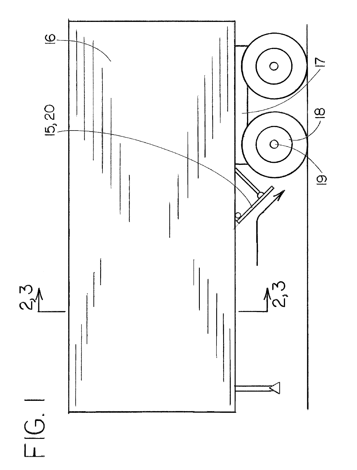
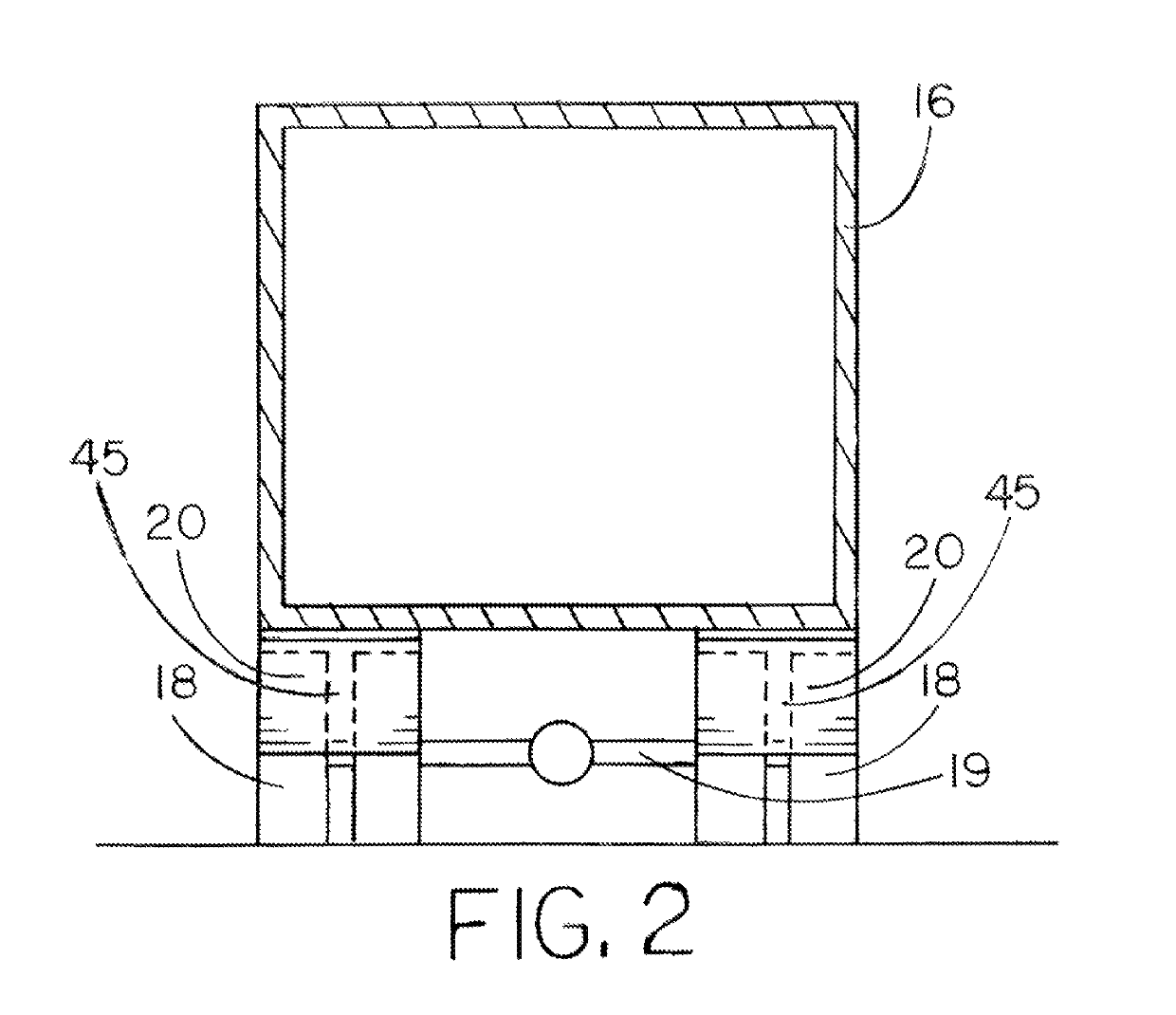
[0087]As shown in FIGS. 1 and 2, an embodiment comprises an inclined aerodynamic wheel deflector panel assembly 20 attached to and mounted underneath the body of a trailer 16 for a commercial vehicle. The inclined wheel deflector panel assembly 20 is located forward of the rear wheel assembly 17 and located directly in front of a trailing wheel set 18 which would otherwise be exposed to headwinds when the vehicle is in forward motion. The inclined wheel deflector panel assembly 20 is planar in shape, mounted inclined in a forwardly-angled orientation with the upper edge more forwardly located and the lower surface located more rearward on the vehicle. The inclined wheel deflector panel assembly 20 spans the lateral width of the trailing wheel set 18 of the trailing rear wheel assembly 17 located on either side of the vehicle. The optimal inclined wheel deflector panel assembly 20 extends downward ideally to no lower than the level of the axle 19 and is located proximal to the tr...

second embodiment

d 3

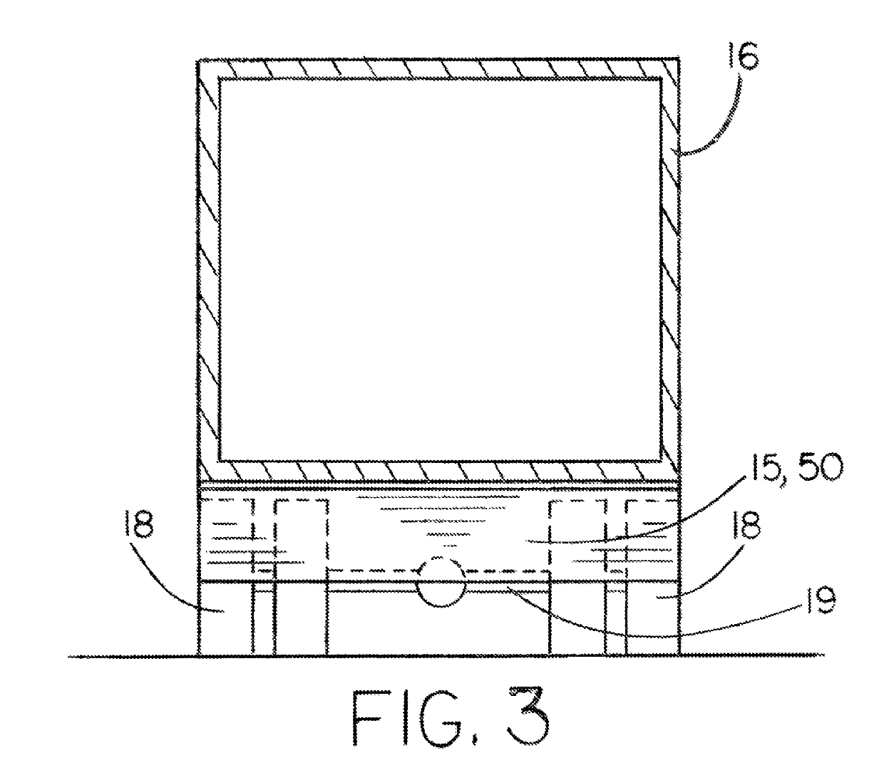
[0110]As shown in FIGS. 1 and 3, an embodiment comprises an inclined aerodynamic deflector panel assembly 15 attached to and mounted underneath the body of a trailer 16 for a commercial vehicle. The inclined deflector panel assembly 15 is located forward of the rear wheel assembly 17 and located in front of trailing wheel sets 18 which would otherwise be exposed to headwinds when the vehicle is in forward motion. The inclined deflector panel assembly 15 is planar in shape, mounted inclined in a forwardly-angled orientation with the upper edge more forwardly located and the lower surface located more rearward on the vehicle. The inclined deflector panel assembly 15 spans the lateral width of the trailer 17, and where aligned directly in front of the wheel sets 18 ideally extends downward to no lower than the level of the axle. The inclined deflector panel assembly 15 is located proximal to the trailing wheel assembly 18 in order to deflect headwinds onto the exposed lower wheel su...

third embodiment

nd 5

[0111]As shown in FIGS. 4 and 5, an embodiment comprises a channeled aerodynamic wheel deflector panel assembly 25 attached to and mounted underneath the body of a trailer 16 for a commercial vehicle. The channeled wheel deflector panel assembly 25 is located forward of the rear wheel assembly 17 and located directly in front of a trailing wheel set 18 which would otherwise be exposed to headwinds when the vehicle is in forward motion. The channeled wheel deflector panel assembly 25 includes a deflector plate 22 which is generally planar in shape, mounted inclined in a forwardly-angled orientation with the upper edge more forwardly-located and the lower surface located more rearward on the vehicle. The channeled wheel deflector panel assembly 25 includes forwardly-projecting end plates 24 attached to either side edge of the deflector plate 22, forming a channeled deflector panel assembly 25 to funnel headwinds directly onto the lower wheel surfaces, minimizing any outwardly defl...


PUM


Abstract

An upper wheel skirt assembly for increasing the propulsive efficiency of a wheeled vehicle having rearward wheels otherwise exposed to headwinds comprising a wheel skirt panel assembly mounted laterally adjacent to a wheel assembly and disposed to shield upper sidewalls of the wheel assembly from headwinds otherwise impinging thereon.

Description

CROSS-REFERENCE TO RELATED APPLICATION[0001]This application is a continuation-in-part of patent application Ser. No. 15 / 430,037, filed Feb. 10, 2017 by Garth L. Magee.BACKGROUNDField[0002]The present embodiment relates to an apparatus for the reduction of aerodynamic drag on vehicles having wind-exposed wheels of a wheel assembly mounted underneath the vehicle body, such as on large commercial trucks.Description of Prior Art[0003]Inherently characteristic of rotating vehicle wheels, and particularly of spoked wheels, aerodynamic resistance, or parasitic drag, is an unwanted source of energy loss in propelling a vehicle. Parasitic drag on a wheel includes viscous drag components of form (or pressure) drag and frictional drag. Form drag on a wheel generally arises from the circular profile of a wheel moving though air at the velocity of the vehicle. The displacement of air around a moving object creates a difference in pressure between the forward and trailing surfaces, resulting in ...

Claims


Application Information

Patent Timeline
Patent Type & Authority Patents(United States)
IPC IPC(8): B62D35/00B62D35/02
CPCB62D35/001B62D35/008B62D35/02Y02T10/82Y02T10/88
Inventor MAGEE, GARTH L.
Owner MAGEE GARTH L
Features
  • R&D
  • Intellectual Property
  • Life Sciences
  • Materials
  • Tech Scout
  • Unparalleled Data Quality
  • Higher Quality Content
  • 60% Fewer Hallucinations
Learn More