Supercharge Your Innovation With Domain-Expert AI Agents!

Wheel fairing deflecting wind onto lower wheel

Active Publication Date: 2015-12-31
MAGEE GARTH L
View PDF4 Cites 2 Cited by
  • Summary
  • Abstract
  • Description
  • Claims
  • Application Information

AI Technical Summary

Benefits of technology

This patent is about a device that can be used on vehicles, like trucks, to reduce the amount of drag and increase efficiency. It uses a wind-deflecting skirt or panel that is placed on the wheel assembly underneath the vehicle. This stops the wind from hitting the upper part of the wheel and directs it towards the lower part, which has less drag. This design also keeps the lower part of the wheel exposed to the wind, which further improves efficiency. Overall, this device helps make vehicles move smoother and faster.

Problems solved by technology

Vehicles having wind-exposed wheels are particularly sensitive to external headwinds reducing propulsive efficiency.
Such propulsive counterforces suffer a mechanical disadvantage against the upper wheel drag forces, since each net force is applied about the same pivot point located at the bottom where the wheel is in stationary contact with the ground.
Furthermore, shielding the lower wheel surfaces can cause a net increase in vehicle drag, and a loss in propulsive efficiency.
As a result, aerodynamic trailer skirts in widespread use today are unnecessarily inefficient, since they generally extend below the level of the axle.
Nevertheless, extended height trailer skirts have been shown to improve propulsive efficiency, since they reduce the aerodynamic pressure on the upper wheel surfaces, which cause the vast majority of wheel drag and virtually all of the loss in vehicle propulsive efficiency due to wheel drag.
As mentioned, diverting wind from impinging the lower wheel surfaces actually increases overall vehicle drag, reducing propulsive efficiency.
Deflecting wind from impinging these lower wheel surfaces transfers the aerodynamic pressure from these slower moving surfaces also suffering a mechanical disadvantage, to faster moving vehicle body surfaces having no mechanical advantage over propulsive counterforces, thereby increasing vehicle drag.
Due to the nonlinear effects of upper wheel drag in rising headwinds, such techniques can produce inaccurate measurements of gains in propulsive efficiency for vehicles having wheels exposed to headwinds.
Thus, as yet this important relationship of upper wheel drag more predominately affecting overall vehicle drag—and especially over lower wheel drag which is often comparitively negligible and suffers a mechanical disadvantage against propulsive counterforces applied at the axle—has gone unrecognized.
Finally, also in the cited art above, several patents such as US 2010 / 0066123 A1, U.S. Pat. No. 8,342,595 B2 and U.S. Pat. No. 8,251,436 B2 depict wind deflecting panels in front of the wheels of the trailer extending to well below the level of the axle, thereby inducing unnecessary vehicle drag by transferring drag from the slower moving lower wheel surfaces having a mechanical disadvantage, to the faster moving vehicle body and frame.

Method used


Image

  • Wheel fairing deflecting wind onto lower wheel
  • Wheel fairing deflecting wind onto lower wheel
  • Wheel fairing deflecting wind onto lower wheel

Examples


first embodiment

FIGS. 1 and 2

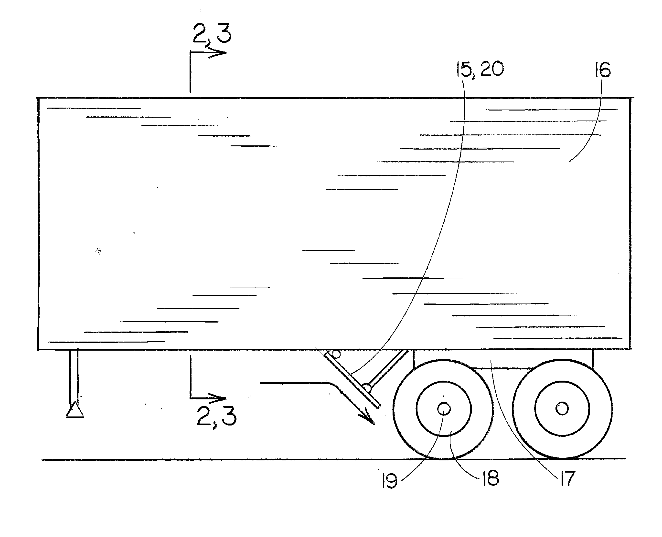
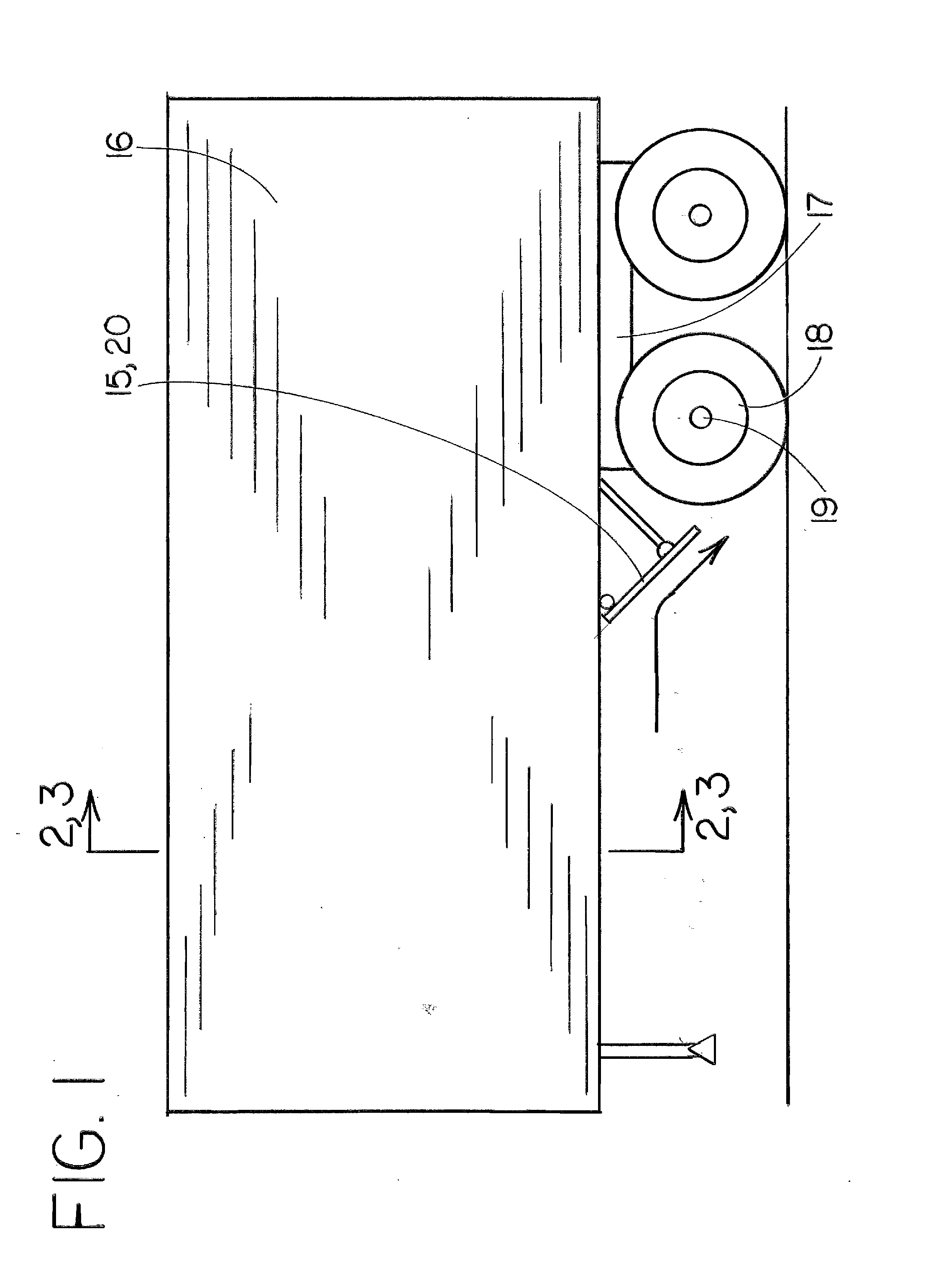
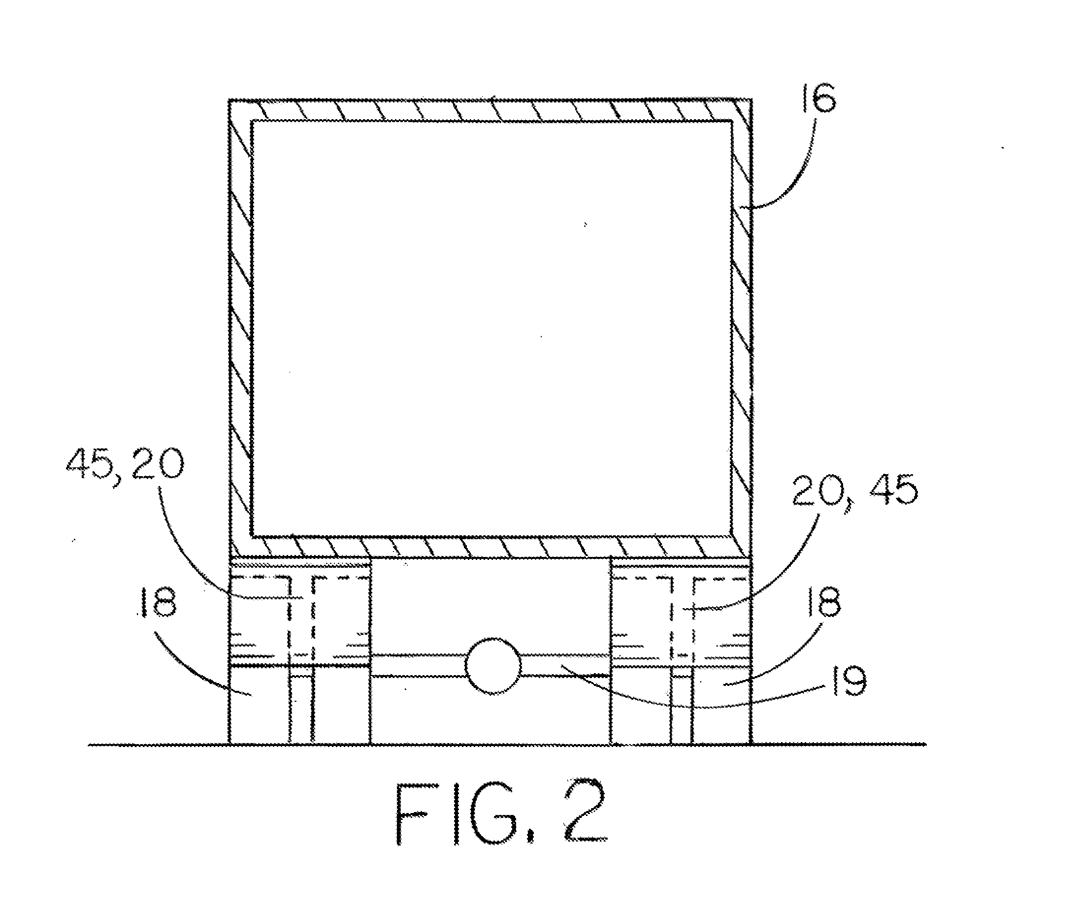
[0071]As shown in FIGS. 1 and 2, an embodiment comprises an inclined aerodynamic wheel deflector panel assembly 20 attached to and mounted underneath the body of a trailer 16 for a commercial vehicle. The inclined wheel deflector panel assembly 20 is located forward of the rear wheel assembly 17 and located directly in front of a trailing wheel set 18 which would otherwise be exposed to headwinds when the vehicle is in forward motion. The inclined wheel deflector panel assembly 20 is planar in shape, mounted inclined in a forwardly-angled orientation with the upper edge more forwardly located and the lower surface more rearwardly located on the vehicle. The inclined wheel deflector panel assembly 20 spans the lateral width of the trailing wheel set 18 of the trailing rear wheel assembly 17 located on either side of the vehicle. The inclined wheel deflector panel assembly 20 extends no lower than the level of the axle 19 and is located proximal to the trailing wheel set ...

second embodiment

FIGS. 1 and 3

[0083]As shown in FIGS. 1 and 3, an embodiment comprises an inclined aerodynamic deflector panel assembly 15 attached to and mounted underneath the body of a trailer 16 for a commercial vehicle. The inclined deflector panel assembly 15 is located forward of the rear wheel assembly 17 and located in front of trailing wheel sets 18 which would otherwise be exposed to headwinds when the vehicle is in forward motion. The inclined deflector panel assembly 15 is planar in shape, mounted inclined in a forwardly-angled orientation with the upper edge more forwardly located and the lower surface more rearwardly located on the vehicle. The inclined deflector panel assembly 15 spans the lateral width of the trailer 17, and where aligned directly in front of the wheel sets 18 extends no lower than the level of the axle. The inclined deflector panel assembly 15 is located proximal to the trailing wheel assembly 18 in order to deflect headwinds onto the exposed lower wheel surfaces, ...

third embodiment

FIGS. 4 and 5

[0084]As shown in FIGS. 4 and 5, an embodiment comprises a channeled aerodynamic wheel deflector panel assembly 25 attached to and mounted underneath the body of a trailer 16 for a commercial vehicle. The channeled wheel deflector panel assembly 25 is located forward of the rear wheel assembly 17 and located directly in front of a trailing wheel set 18 which would otherwise be exposed to headwinds when the vehicle is in forward motion. The channeled wheel deflector panel assembly 25 includes a deflector plate 22 which is generally planar in shape, mounted inclined in a forwardly-angled orientation with the upper edge more forwardly-located and the lower surface more rearwardly-located on the vehicle. The channeled wheel deflector panel assembly 25 includes forwardly-projecting end plates 24 attached to either side edge of the deflector plate 22, forming a channeled deflector panel assembly 25 to funnel headwinds directly onto the lower wheel surfaces, minimizing any out...


PUM


Abstract

An upper wheel fairing for increasing the propulsive efficiency of a wheeled vehicle having wheels otherwise exposed to headwinds, comprising a deflector panel or skirt assembly mounted upstream in front of a rearward wheel set, extending downward not lower than the axle, and arranged to deflect headwinds from impinging upon the high drag-inducing upper wheel surfaces downward onto the low-drag lower wheel surfaces.

Description

BACKGROUND [0001]1. Field[0002]The present embodiment relates to an appartus for the reduction of aerodynamic drag on vehicles having wind-exposed wheels of a wheel assembly mounted underneath the vehicle body, such as on large commercial trucks.[0003]2. Description of Prior Art[0004]Vehicles having wind-exposed wheels are particularly sensitive to external headwinds reducing propulsive efficiency. Drag force on exposed wheels increases more rapidly on upper wheel surfaces than on vehicle frame surfaces, causing a non-linear relation from rising wind speeds between net drag forces on vehicle frame surfaces versus net drag forces on vehicle wheel surfaces.[0005]Since upper wheel surfaces are moving against the wind at more than the vehicle speed, the upper wheel drag forces contribute more and more of the total vehicle drag as external headwinds rise. Thus, as external headwinds rise, a greater fraction of the net vehicle drag is shifted from vehicle frame surfaces to upper wheel sur...

Claims


Application Information

Patent Timeline
IPC IPC(8): B62D35/02
CPCB62D35/02B62D35/001Y02T10/82Y02T10/88B62D35/008
Inventor MAGEE, GARTH L.
Owner MAGEE GARTH L
Features
  • R&D
  • Intellectual Property
  • Life Sciences
  • Materials
  • Tech Scout
  • Unparalleled Data Quality
  • Higher Quality Content
  • 60% Fewer Hallucinations
Learn More