Fixed-wing vtol aircraft with rotors on outriggers

Inactive Publication Date: 2017-08-24
YUEN MELVILLE
View PDF0 Cites 14 Cited by
  • Summary
  • Abstract
  • Description
  • Claims
  • Application Information

AI Technical Summary

Benefits of technology

[0005]The rotors can be tilted over ninety degrees from the vertical position forwards and backwards, sideways if needed for lateral movement. The outriggers can be configured in various ways depending upon how many rotors are used and where the engines are located. Placing rotors on outriggers in the spaces least obstructed by the wings and fuselage reduces drag which increases efficiency and also offers a flexible platform for various hybrid designs.
[0006]Multiple rotors has the advantage of smaller diameter and lighter rotors blades, lower structural requirements, smaller gears, reduced weight, better stability

Problems solved by technology

Fixed-wing VTOL aircraft present the most difficult challenges in aerospace engineering, as the transition between vertical, direct-thrust, flight and horizontal, wing

Method used


Image

  • Fixed-wing vtol aircraft with rotors on outriggers
  • Fixed-wing vtol aircraft with rotors on outriggers
  • Fixed-wing vtol aircraft with rotors on outriggers

Examples


Example

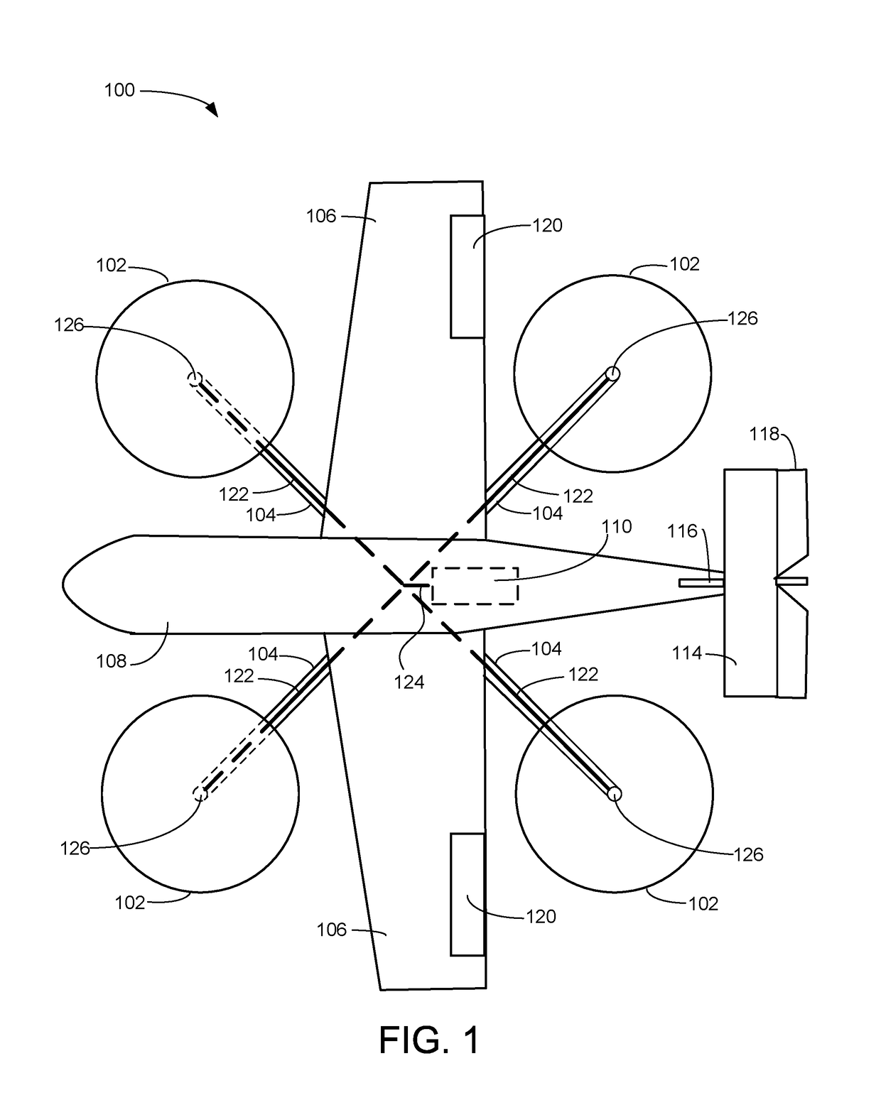
[0026]FIG. 1 is a top plan diagrammatic view illustrating an exemplary embodiment of the fixed-wing VTOL aircraft 100 with rotors 102 on outriggers 104, according to a preferred embodiment of the present invention. Fuselage 108, including structural members therein, supports wings 106 with flight control surfaces 120 (such as ailerons 120) and a vertical stabilizer 116 further supporting horizontal stabilizer 114 having a flight control surface 118 (such as an elevator 118). Fuselage 108 further supports outriggers 104 which house drive shafts 122 coupled between motor output shaft 124 and rotational couplings 126. In some embodiments, fuselage 108 may support an emergency ballistic parachute that can deploy if the aircraft 100 is disabled. Motor output shaft 124 is driven by motor 110, which is located within the fuselage 108. Coupling between the motor output shaft 124 and the drive shafts 122 may, in various embodiments, be of any suitable configuration, within the constraints of...


PUM


Abstract

The VTOL aircraft of the present invention has fixed-wings which can be monoplane, biplane or tri-plane and tiltable rotors on outriggers which extend from the fuselage and/or wings. The rotors on the outriggers can be driven by engines located in the fuselage or wings via a transmission system such as a shaft, pulley, or pressurized air using pumps. If rotors are driven by jets at the tips, fuel is fed through pipes inside of the outriggers. The rotors and engines can be located at the ends of the outriggers or the rotors may be separate from the engines and tilting only the rotors reduces structural requirements and weight of the aircraft. The rotors can be tilted over ninety degrees from the vertical position forwards and backwards, sideways if needed for lateral movement. The outriggers can be configured in various ways depending upon how many rotors are used and where the engines are located. Placing rotors on outriggers in the spaces least obstructed by the wings and fuselage reduces drag which increases efficiency and also offers a flexible platform for various hybrid designs.

Description

FIELD OF ART[0001]The present invention relates to a fixed-wing vertical take-off and landing (VTOL) aircraft having rotors on outriggers. The present invention more particularly relates VTOL aircraft having pivotal propulsion elements.BACKGROUND OF THE INVENTION[0002]Fixed-wing VTOL aircraft present the most difficult challenges in aerospace engineering, as the transition between vertical, direct-thrust, flight and horizontal, wing-borne, flight raises serious stability problems. The Harrier aircraft uses vectored thrust from jet engine compressor bleed air for vertical, direct-thrust, flight and traditional jet engine power for wing-borne flight. The Osprey aircraft uses tilt rotors on the ends of fixed-wings for vertical takeoff and tilts the engines and rotors to transition to wing-borne flight. In vertical flight, part of the rotor-propelled air impinges on the top surface of the wing, reducing effective thrust. In wing-borne flight, the wing receives rotor-propelled air from o...

Claims


Application Information

Patent Timeline
IPC IPC(8): B64C29/00B64D27/02
CPCB64D27/02B64C29/0033B64D35/00
Inventor YUEN, MELVILLE
Owner YUEN MELVILLE
Why Eureka
Try Eureka