Tunable Fluid Flow Generator

a generator and fluid flow technology, applied in the direction of electric generator control, machines/engines, mechanical equipment, etc., can solve the problems of reducing fuel efficiency, limiting the practicality of their application in certain fields, and the aerodynamic limitations of the turbine are not ideal for vehicular applications, so as to reduce or prevent the movement of the contact portion

Active Publication Date: 2013-08-22
HSU SEAN N
View PDF18 Cites 14 Cited by
  • Summary
  • Abstract
  • Description
  • Claims
  • Application Information

AI Technical Summary

Benefits of technology

[0019]It is another object of an embodiment of the present invention to provide a braking mechanism and method for a fluid flow generator by allowing the system operation to be damped or restricted so as to reduce or prevent movement of the contacting portion of the fluid flow generator.

Problems solved by technology

But the large cross-sections of these traditional designs increase the amount of wind resistance presented by the generators, limiting the practicality of their application in certain fields.
For example, the prior art describes a vehicle having a wind tunnel and turbine generator, but the aerodynamic limitations of the turbine are not ideal for vehicular applications.
Those disclosures created wind resistances which would substantially decrease fuel efficiency.
The designs introduce drag and a blocking obstacle in the fluid flow and require supporting structures which greatly affect the cross-sectional aerodynamics.
Prior devices typically required large structures and / or large motive forces, which often mean that the devices could only be operated under certain conditions or in certain locations.
These devices also typically have many moving parts, which increase the need for maintenance and the potential for breakdown.
These devices also face increased stresses as motive forces increased, requiring designs or use that compensated for high speed or shut down to avoid damage.
Furthermore, the output from these devices varies substantially with the relative velocity of the medium, often requiring the design to compensate for velocities outside of a tolerance range.
For example, the aerodynamic cost from the cross-sectional shapes of many of these designs is too high for certain applications, such as in vehicular applications.
Additionally, the mechanical complexities of some of the devices have been a noted concern, resulting in high cost, difficult maintenance, and overall complicated manufacturing.
Other designs are unidirectional and not able to be accommodating of changing directions of fluid flow without additional rotational structures.
Some of the designs are also dependent on the speed of fluid flow, with limited efficiency or effectiveness outside of a narrower range of preferred flow speeds.
Some designs may even break down at excessive speeds, as has been shown in test flights of generators at altitude.

Method used


Image

  • Tunable Fluid Flow Generator
  • Tunable Fluid Flow Generator
  • Tunable Fluid Flow Generator

Examples


Embodiment Construction

[0050]Some embodiments of the invention are described below in further detail with respect to the Figures.

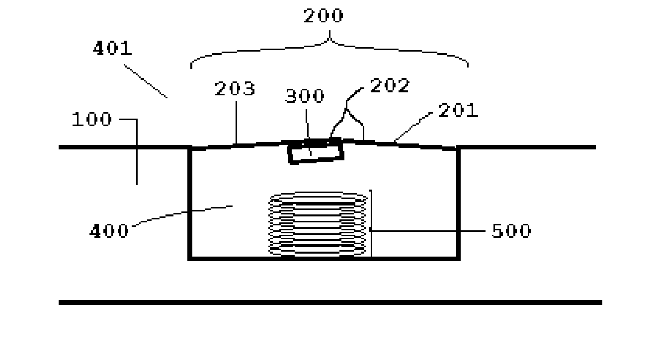
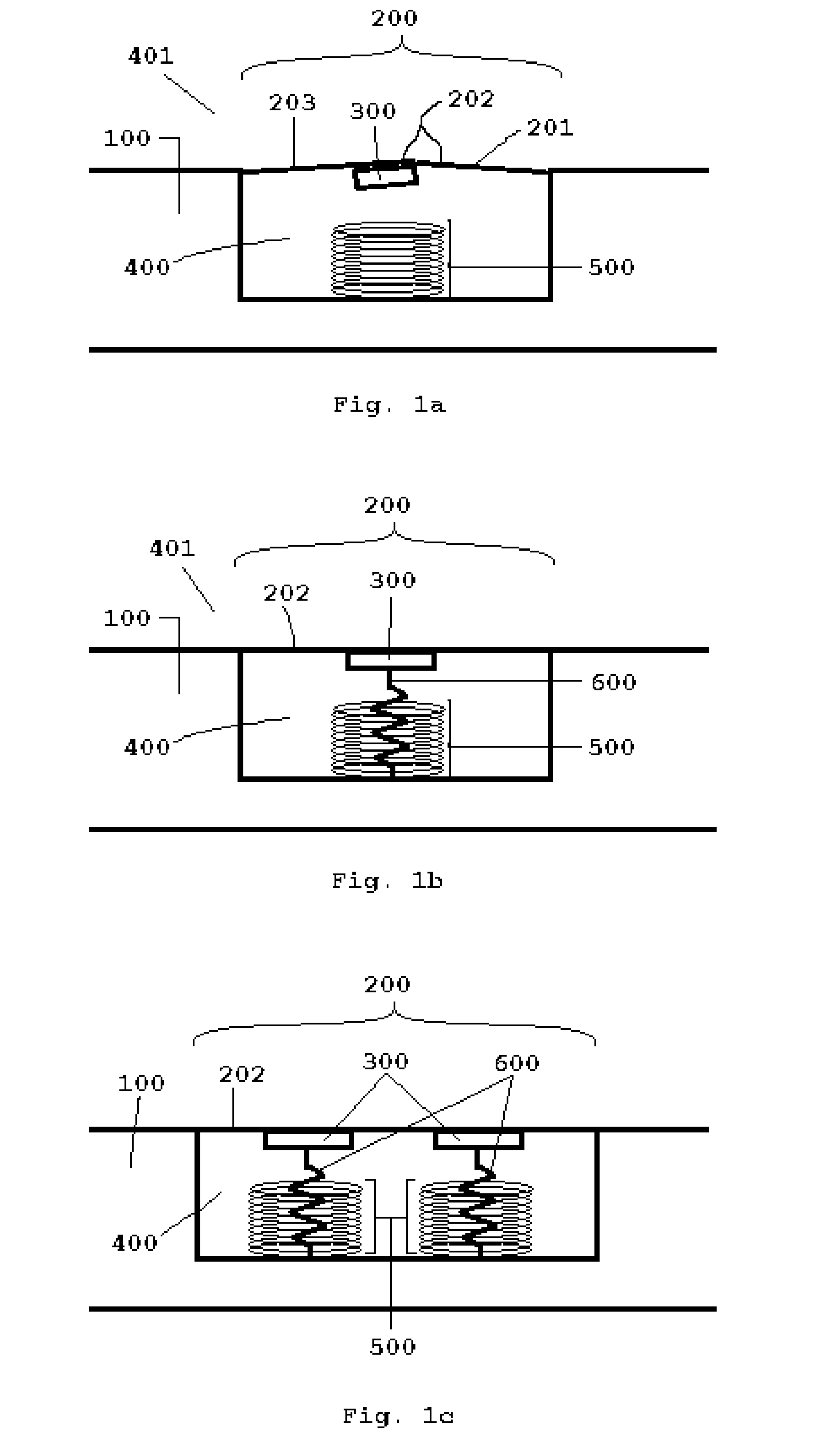
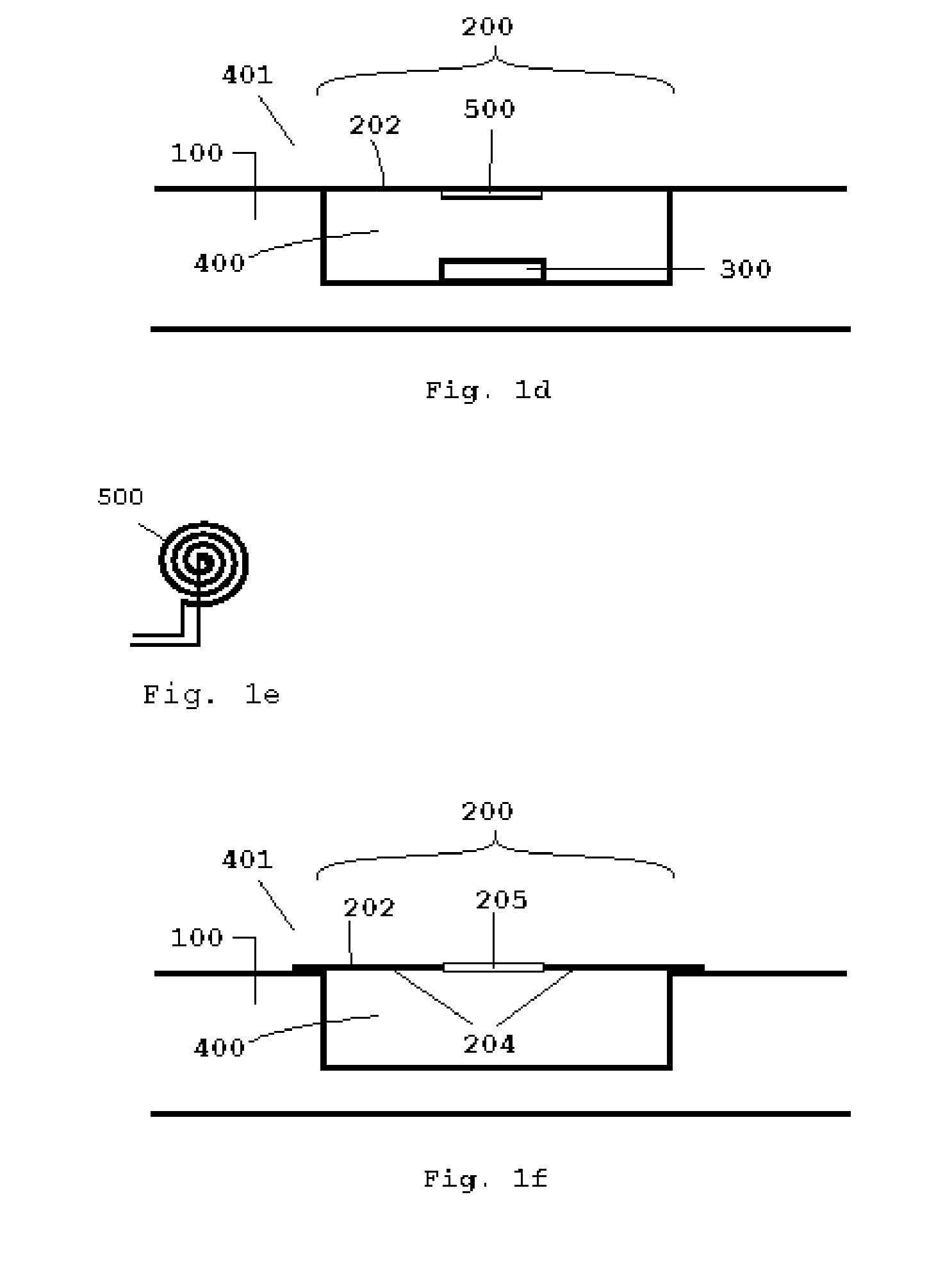
[0051]According to an aspect of an embodiment of the invention, a generator has a surface structure or contacting portion relative to a base structure or frame and is positionable within a field of flow. Preferably, the surface structure is connected to the base structure along the leading edge of the surface structure relative to the direction of flow such that the field of flow is directed substantially over the surface structure. The surface structure can be shaped in a number of ways when taking into account aerodynamics, including curvilinear, faceted, and angular shapes. Many structural shapes are known within the art and can be incorporated here to provide a desired level of aerodynamics for the particular application, such as aerofoils, wing shapes, spoilers, riblets, curved leading edges, etc. The surface structure design also helps to generate a motive force from the f...


PUM


Abstract

A tunable generator has a surface structure for contacting an exterior fluid flow relative to a base structure. The contacting surface structure also has an electrogenerative portion positioned relative to the contacting structure and the base structure. The electrogenerative portion is preferably a piezoelectric or electromagnetic structure, although other types of structures are known within the art. The contacting surface is mechanically coupled to portions of the base structure through one or more elastic elements. The various portions of the base structure can be positioned relative to other base structure portions to alter the elasticity of the system or the tensioning of the elastic elements. The field of flow exerts forces upon the contacting structure which causes movement in the contacting surface structure relative to the base structure through the electrogenerative portion.

Description

CROSS-REFERENCE TO RELATED APPLICATIONS[0001]This application is a continuation-in-part from U.S. non-provisional patent application Ser. No. 13 / 551593, filed Jul. 17, 2012, which claims priority to U.S. provisional patent application Ser. No. 61 / 508694, filed Jul. 18, 2011.BACKGROUND[0002]1. Field of the Invention[0003]The preferred embodiments of the invention are directed to the field of power generation.[0004]2. Description of the Related Art[0005]Generators harnessing energy from a fluid flow (such as air) are known within the art, however such generators typically have turbines or propellers which have a large cross-section. The movement of the medium creates a motive force upon the turbine or propeller, which is connected to a device to convert the movement into electricity. But the large cross-sections of these traditional designs increase the amount of wind resistance presented by the generators, limiting the practicality of their application in certain fields.[0006]For exa...

Claims


Application Information

Patent Timeline
Patent Type & Authority Applications(United States)
IPC IPC(8): F03B17/06
CPCY02E10/28F03B17/06F03G7/08Y02E10/70F03D5/00Y02E10/72Y02E10/20F03D9/00F03D5/06
Inventor HSU, SEAN NEAN
Owner HSU SEAN N
Why Eureka
Try Eureka