
A floatable unit for evacuation purposes

A technology of equipment and purpose, applied in the field of floatable equipment, can solve the problem of occupying deck space, etc., and achieve the effect of high directional stability, easy towing and driving

Active Publication Date: 2010-05-26
VIKING LIFE SAVING EQUIP
View PDF1 Cites 15 Cited by
  • Summary
  • Abstract
  • Description
  • Claims
  • Application Information

AI Technical Summary

Problems solved by technology

Lifts and brackets / bases also take up a lot of deck space

Method used


Image

  • A floatable unit for evacuation purposes
  • A floatable unit for evacuation purposes
  • A floatable unit for evacuation purposes

Examples


Embodiment Construction

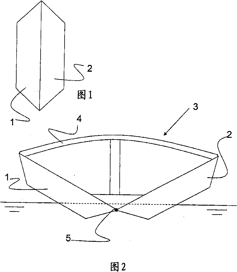
[0072] exist figure 1 , an embodiment of a floatable device in a stored state is schematically shown in front view. In this embodiment, the two shells 1, 2 house the inflatable structure. The housing is fabricated from a rigid or semi-rigid material which, for the embodiment described below, may be fiberglass reinforced plastic, composite material, metal, or combinations thereof.

[0073] The two shells 1 , 2 and the inflatable structure contained inside can be placed on the deck of a ship known per se or can be placed in a rack system also known per se. Neither the deck nor the bracket system is shown.

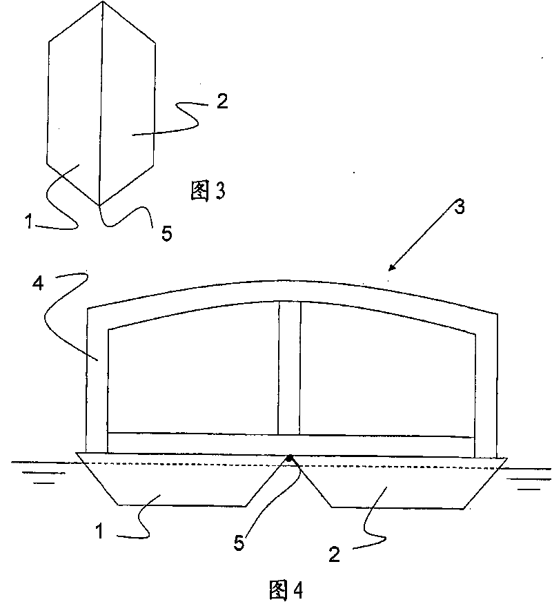
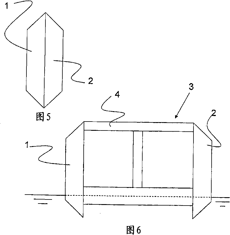
[0074] exist figure 2 In , an embodiment of a floatable device 3 according to the invention is schematically shown in front view during an evacuation state. According to the idea of ​​the invention, the inflatable structure of the floatable device is inflated and the hulls 1 , 2 are connected to the inflatable structure 4 , whereby the hulls 1 , 2 act as hull parts of th...


PUM


Abstract

The present invention relates to a floatable unit for evacuation purposes, which in a storage situation comprises at least two shells made of rigid or semi-rigid material, said shells being adapted to accommodate a deflated structure. Said deflated structure of the unit, during an evacuation situation, is inflated and the shells are attached to the inflated structure whereby the shells operate ashull parts for the floatable unit.

Description

technical field [0001] The present invention relates to a floatable device for evacuation purposes, said floatable device comprising, in a stored state, at least two shells made of rigid or semi-rigid material, said shells being adapted to accommodate an inflatable structure. Background technique [0002] Evacuation of ship passengers and crew into inflatable life rafts or lifeboats is known in emergency situations. [0003] Life rafts are usually stored in containers in a deflated state on the deck of a vessel. In this stored state, the container does not take up much ground or space on deck. Additionally, a rack system may be provided on the deck of a vessel for housing one or more containers. During an evacuation situation, the container is either thrown overboard into the water, after which it is inflated, or it is inflated on board and then lowered into the water. Then, the evacuation of personnel can be carried out. [0004] Inflatable life rafts are now suitable f...

Claims


Application Information

Patent Timeline
Patent Type & Authority Applications(China)
IPC IPC(8): B63C9/02B63C9/04B63B7/08
CPCF01D9/02F15D1/06F05D2220/32B63C2009/042F01D25/30F05D2220/31F15D1/0005F15D1/0025B63B2001/145Y02T50/672F05D2250/292B63C9/04F05D2250/323F05D2250/232B63B7/082B63C9/02Y02T50/60
Inventor O·安德森
Owner VIKING LIFE SAVING EQUIP
Learn More