Medical/surgical waste collection unit with a light assembly separate from the primary display, the light assembly presenting information about the operation of the system by selectively outputting light

a technology for medical/surgical waste and waste collection, which is applied in the field of system for collecting medical and surgical waste, can solve the problems of clutter, reduced extent to which the suction tubing is present around the surgical personnel, and reduced the extent to which the operating room personnel are potentially exposed to the materials collected by the system

Active Publication Date: 2019-09-24
STRYKER CORP
View PDF40 Cites 173 Cited by
  • Summary
  • Abstract
  • Description
  • Claims
  • Application Information

AI Technical Summary

Benefits of technology

[0009]This invention is directed to a new and useful waste collection system for collecting waste generated during a medical or surgical procedure. The system of this invention presents information about the operating state of the system that is easy to both view and mentally process.
[0014]The system of this invention provides a means to readily determine information about a state of the system without requiring the individual to look directly at the light emitter. In versions of the invention wherein the light is sourced to a fiber optic core integral with the suction tube, the light is sourced to a location in close in the proximity to the hand of the person performing the procedure. This means that the individual does not have to divert his / her eyes away from the location where the procedure is being performed to perceive the transmitted light. This reduces the extent to which the individual has to break his / her concentration to obtain information about the waste or smoke collection process.
[0016]A further feature of this invention is that different sub-assemblies of the waste collection unit of this invention will emit light in different colors, in different patterns. When this light is transmitted to a fiber optic core integral with the line connected to the sub-assembly, the light is emitted by the device attached to the distal end of the line. This means that personnel by simply looking at the light emitted by the line or attached device can readily determine the unit sub-assembly to which the line is attached.

Problems solved by technology

This reduces the extent to which the suction tubing, which invariably also functions as operating room clutter, is present around the surgical personnel.
This reduces the extent to which operating room personnel are potentially exposed to the materials collected by the system.
This is desirable because these solids can potentially clog the downstream components of the system.
Having to perform these actions, mentally process the displayed information, and then return his / her head to the patient can interrupt the flow of the procedure.
This smoke is generated in some procedures when electrocautery tools are applied to tissue.
An unintended consequence of providing plural tubes to draw away these liquid and gaseous state fluids is that it can be confusing for the personnel performing the procedure to determine which tube is connected to which waste evacuation component.

Method used


Image

  • Medical/surgical waste collection unit with a light assembly separate from the primary display, the light assembly presenting information about the operation of the system by selectively outputting light
  • Medical/surgical waste collection unit with a light assembly separate from the primary display, the light assembly presenting information about the operation of the system by selectively outputting light
  • Medical/surgical waste collection unit with a light assembly separate from the primary display, the light assembly presenting information about the operation of the system by selectively outputting light

Examples


Embodiment Construction

I. Waste Collection and Smoke Evacuation Unit

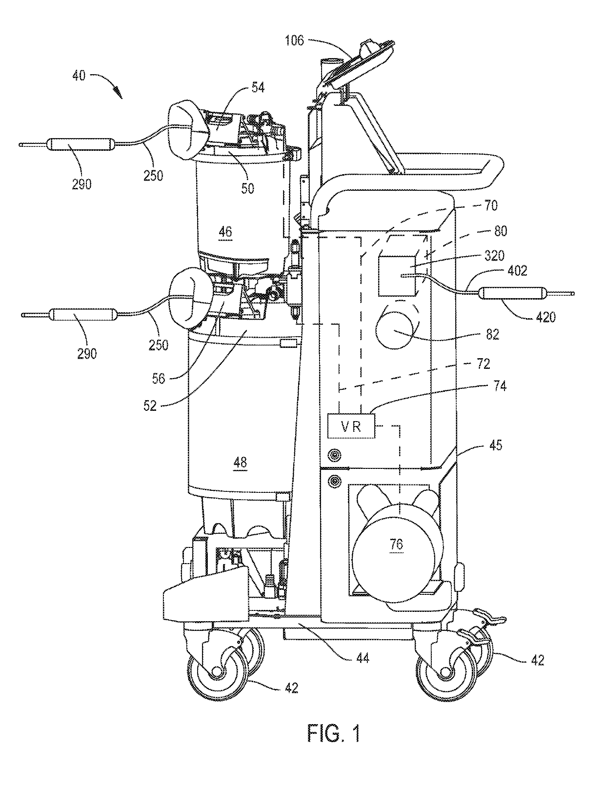
[0062]FIG. 1 illustrates a waste collection unit 40 constructed in accordance with this invention. The unit 40, sometimes referred to as a rover, includes a base 44. The cover and doors that normally conceal the components of the unit 40 are not present so that the interior components of the unit can be seen. Wheels 42, attached to the base 44, provide unit 40 with mobility. A chassis 45 extends upwardly from the base 44. The chassis 45 is the structural frame of unit 50 to which other components of the unit are mounted. Two canisters 46 and 48 are mounted to the base 44. Canister 46 is disposed over canister 48. Canister 46 has a relatively small interior volume, between 1 and 10 liters. Canister 48 typically has an interior volume larger than that of canister 46. In some versions of the invention canister 48 has a volume between 10 and 40 liters. Not illustrated and not part of the present invention is a valve located between the canist...


PUM


Abstract

A waste collection unit (40) with a primary display (106) on which information about the operation of the unit is presented. In addition to the primary display there is a light assembly (662) adjacent the fitting (614) to which a suction line is attached. The light assembly emits light of selectively colors or in a selected pattern based on an operation state of the waste collection unit.

Description

FIELD OF THE INVENTION[0001]This invention is generally related to a system for collecting medical and surgical waste. More particularly, the system of this invention monitors the status of the operation of the waste collection unit and, based on this information, outputs light in different colors and patterns.BACKGROUND OF THE INVENTION[0002]A byproduct of the performance of some medical and surgical procedures is the generation of liquid and semi-solid waste. This waste includes body fluids, such as blood, and irrigating solution introduced to the body site at which the procedure is performed. This waste also includes bits of tissue and small pieces of the surgical material that may be present at the site. Ideally, the waste is collected upon generation so the waste neither visually obstructs nor fouls the surgical site nor becomes a biohazard in the operating room or other location at which the procedure is being performed.[0003]A number of systems are available for use by surgic...

Claims


Application Information

Patent Timeline
Patent Type & Authority Patents(United States)
IPC IPC(8): A61M1/00
CPCA61M1/0001A61M1/0086A61M1/0027A61M2205/587A61M2205/3389A61M2205/584A61M2205/502A61M2209/084A61M1/732A61M1/60A61M1/64A61M1/86
Inventor REASONER, STEPHEN J.CHILDERS, ROBERT W.GAMHEWAGE, CHAMARAHALL, MICHAEL W.HOGAN, NATHAN K.MACLACHLAN, BRIAN J.MILLER, MICHAEL J.
Owner STRYKER CORP
Why Eureka
Try Eureka