Eureka AIR delivers breakthrough ideas for toughest innovation challenges, trusted by R&D personnel around the world.

Clamp for clamping a cord on account of tension in the cord

Active Publication Date: 2019-10-29
CAPS INT
View PDF9 Cites 3 Cited by
  • Summary
  • Abstract
  • Description
  • Claims
  • Application Information

AI Technical Summary

Benefits of technology

The invention provides a clamp that can securely hold cords or wires in place without causing excessive pressure load on the hinge, even at smaller dimensions. The clamp can be easily pressed down using a finger, and is comfortable to use. The technical effects of the invention are improved durability and ease of use for a range of wire sizes and configurations.

Problems solved by technology

When reducing the construction in size, there is a risk that the pressure force causes the hinge to deflect laterally, resulting in failure of the hinge.

Method used


Image

  • Clamp for clamping a cord on account of tension in the cord
  • Clamp for clamping a cord on account of tension in the cord
  • Clamp for clamping a cord on account of tension in the cord

Examples


Embodiment Construction

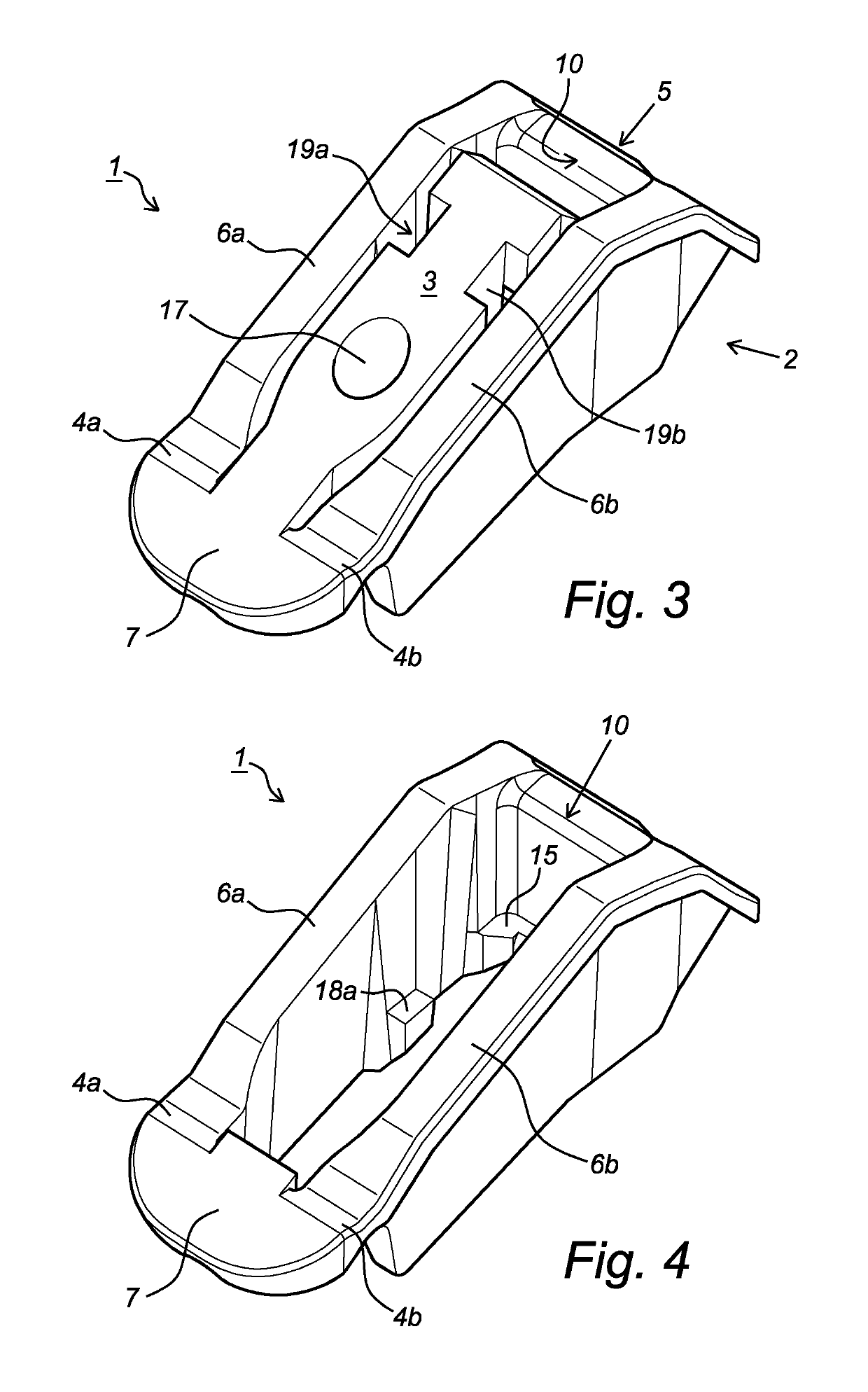
[0034]The clamp according to the invention which is denoted overall by reference numeral 1 and which is illustrated in FIGS. 1, 2 and 3, comprises a frame 2 and a clamping body 3, which are connected to each other by two hinges 4a, 4b. The frame 2 is in the shape of a U and has a bridge 5 and two legs 6a, 6b. The clamping body 3 is provided with a widened part 7, with the hinges 4a, 4b being formed between the ends of the two legs 6a, 6b and the widened part 7 of the clamping body 3. The entirety of the clamp is made of plastic, preferably of POM, preferably by means of injection-molding. The hinges have a stiffness which is such that the clamping body 3 assumes a neutral position with respect to the frame 2 without external forces acting on it, as is illustrated in the figures.

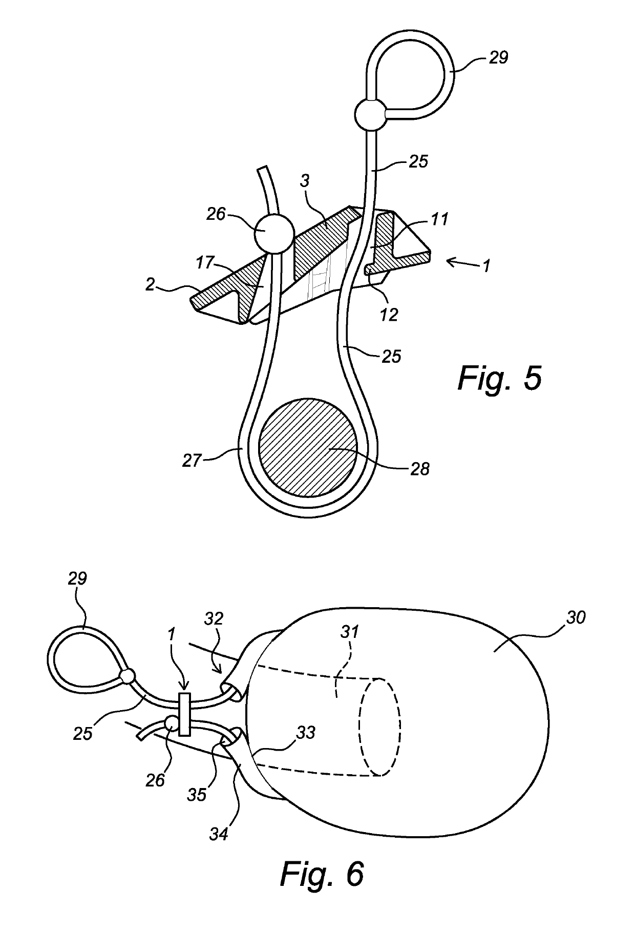
[0035]As can be seen most clearly in FIG. 2, the bridge 5 of the frame 2 is provided with a clamping surface 10 on the inner side. A cord duct 11 is formed between the clamping surface and the clamping body 3...


PUM


Abstract

Clamp (1) for clamping a cord in tension, in which the clamp comprises a U-shaped elongate frame (2) with an elongate recess and an elongate clamping body (3) which is connected to the frame and extends in the recess of the frame, in which—a cord duct (11) is formed in the recess between the clamping body and a clamping surface (10) of the frame, the clamping body is configured to be carried along by a cord passed through the cord duct, in which the distance between the clamping body and the clamping surface decreases when the clamping body is moved, the clamping body has a widened part (7) at one end and in which a hinge (4) is provided between the legs (6a, 6b) of the frame and the widened part of the clamping body, the axis of rotation of which extends at right angles to the longitudinal direction of the frame.

Description

CROSS-REFERENCE TO RELATED APPLICATIONS[0001]This application is the United States national phase of International Application No. PCT / NL2014 / 050828 filed Dec. 3, 2014, and claims priority to Dutch Patent Application No. 2011902 filed Dec. 5, 2013, the disclosures of which are hereby incorporated in their entirety by reference.BACKGROUND OF THE INVENTIONField of the Invention[0002]The invention relates to a clamp for clamping a cord at a clamping location of the cord on account of a tension prevailing at a tension side of the clamping location in the cord.Description of Related Art[0003]Such clamps are generally known in the form of sheet clamps which are used in sailing and which are provided with two wheel segments, between which a sheet is guided which causes the wheel segments to rotate when it is being tightened until they reach a position in which the wheel segments clamp the sheet.[0004]Furthermore, FR-B-2 802 598 shows a clamp for clamping a cord at a clamping location of th...

Claims


Application Information

Patent Timeline
IPC IPC(8): A22B5/00F16G11/10F16G11/14
CPCF16G11/105F16G11/14A22B5/0005A22B2005/0011
Inventor HEURMAN, ERWIN HERMAN GERHARDUSGEENEN, KAMIEL REINIER ZALEVERHEUL, SIMON ALEXANDERVAN BERKUM, ANDRIESGIJSBERS, PIM JOHAN HANS
Owner CAPS INT
Why Eureka
Eureka Blog
Learn More