Pneumatic vehicle tire

a technology for pneumatic vehicles and tires, applied in the direction of tires, tyre parts, tread bands/patterns, etc., can solve the problem of reducing the rolling resistance of the rubber compound in the shoulder portions, and achieves the effect of reducing the rolling resistance, reducing the impact of the tire, and reducing the impact resistan

Active Publication Date: 2019-10-29
CONTINENTAL REIFEN DEUTSCHLAND GMBH
View PDF15 Cites 3 Cited by
  • Summary
  • Abstract
  • Description
  • Claims
  • Application Information

AI Technical Summary

Benefits of technology

[0008]Accordingly, the stiffer rubber compound with the greater dynamic modulus of elasticity E′ from the central portion is therefore continued below the softer compounds in the shoulder portions. It has been determined that this measure results in a special deformation behavior of the tire during rolling, the deformation behavior being highly advantageous especially for the handling properties, in particular the cornering stiffness, with a low rolling resistance remaining. Furthermore, the stiffer extensions make it possible to configure the rubber compound in the shoulder portions to be particularly low in rolling resistance. Furthermore, tread substructure is understood as meaning the substructure of the tread or the component directly adjoining radially within the tread, such as, for example, the tread base, if the tread is formed from cap and base, or a lower plate.
[0009]According to a preferred embodiment, the extensions have an at least substantially constant thickness of between 1.0 mm and 2.0 mm. With extensions of a thickness within this range, the conflict of objectives between low rolling resistance and high cornering stiffness can be particularly readily resolved.
[0012]In order to obtain particularly balanced and good results with respect to low rolling resistance and better cornering stiffness, it is advantageous if the central portion has a width of between 30% and 70% of the width of the ground contact area, depending on the tire width. In the case of wider tires, the central portion is configured to be relatively wider than in the case of narrower tires; in contrast, the width of the two shoulder portions is substantially independent of the tire width and is preferably approximately identical in size for wider and narrower tires.
[0014]The two extensions of the central portion permit the rubber compound of the shoulder portions to be configured to be particularly low in rolling resistance. The shoulder portions can therefore be composed of a rubber compound, the rebound resilience of which corresponds at least to the rebound resilience of the rubber compound in the central portion, and it is in particular advantageous if the rebound resilience of the rubber compound in the shoulder portions is greater than the rebound resilience of the rubber compound in the central portion.
[0017]In particular, the dynamic modulus of elasticity E′ of the rubber compound of the shoulder portions should be between 2.0 N / mm2 and 6.4 N / mm2, in particular between 3.0 N / mm2 and 5.7 N / mm2. The dynamic modulus of elasticity E′ of the rubber compound of the central portion should be between 3.9 N / mm2 and 8.1 N / mm2, in particular between 5.2 N / mm2 and 7.7 N / mm2. Particularly good cornering stiffness of the pneumatic vehicle tire is ensured precisely in these regions.
[0018]In order to keep the rolling resistance as low as possible, it is advantageous if the rubber compound of the central portion has a rebound resilience which is between 10% and 80% lower than the rebound resilience of the rubber compound of the shoulder portions. The rebound resilience of the rubber compound of the two shoulder portions should be between 40% and 90%, in particular between 50% and 80%. The rebound resilience of the rubber compound of the central portion should be between 15% and 70%, in particular between 20% and 60%.

Problems solved by technology

Furthermore, the stiffer extensions make it possible to configure the rubber compound in the shoulder portions to be particularly low in rolling resistance.

Method used


Image

  • Pneumatic vehicle tire

Examples


Embodiment Construction

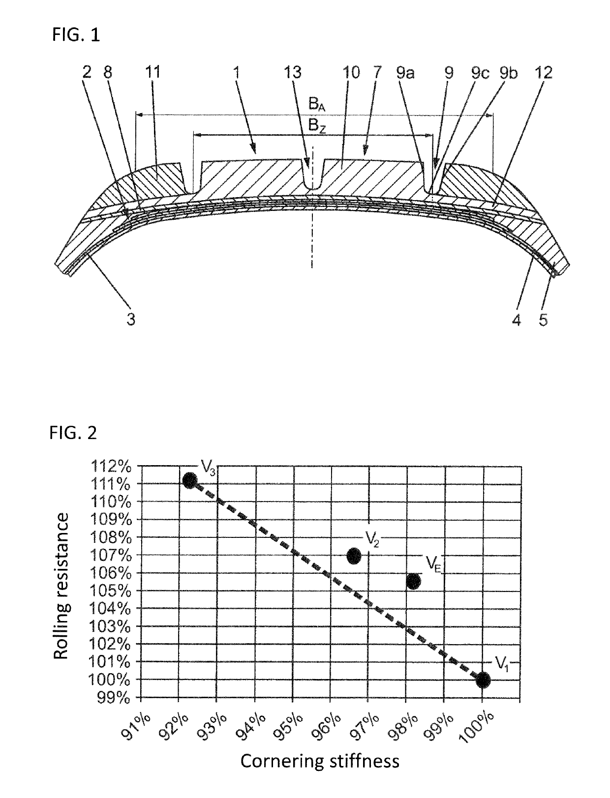
[0022]Pneumatic vehicle tires configured in accordance with the disclosure are provided or are particularly readily suitable for passenger vehicles, vans and the like. Of the customary components of a tire for passenger vehicles, FIG. 1 shows a tread 1, a belt 2, a radial ply casing 3, and an air-tight inner layer 4. In the example, the belt 2 has two belt plies which, in a known manner, can contain steel cord as a reinforcement. The ply casing 3 is reinforced in the customary manner with textile reinforcements. The belt 2 can be covered by a belt bandage (not shown) including rubberized textile reinforcements encircling the tire in the circumferential direction. Furthermore, the axially outer portions of side walls 5 are illustrated. Bead regions with bead cores, core profiles and the like are not shown.

[0023]The tread 1 can be configured as a single part, from a single rubber layer, or can be composed of two rubber layers, namely of a radially outer rubber layer, a tread cap 7, an...


PUM

PropertyMeasurementUnit
Tgaaaaaaaaaa
Tgaaaaaaaaaa
elongationaaaaaaaaaa

Abstract

A pneumatic vehicle tire for passenger cars, vans or the like has a radial carcass, a multi-ply belt, and a profiled tread that, as viewed in the axial direction, has a central portion and two shoulder portions. The shoulder portions include a rubber mixture that has a lower dynamic modulus of elasticity E′ (at 55° C. and 8% elongation according to DIN 53513) than the central portion. The central portion has extensions at the base thereof, running laterally substantially parallel to the tread substructure and radially inside and across the width of the shoulder portions.

Description

CROSS REFERENCE TO RELATED APPLICATIONS[0001]This application is a continuation application of international patent application PCT / EP2014 / 052769, filed Feb. 13, 2014, designating the United States and claiming priority from German application 10 2013 103 367.9, filed Apr. 4, 2013, and the entire content of both applications is incorporated herein by reference.FIELD OF THE INVENTION[0002]The disclosure relates to a pneumatic vehicle tire for passenger vehicles, vans or the like, with a radial ply casing, a multi-ply belt and a profiled tread which, as viewed in the axial direction, has a central portion and two shoulder portions, wherein the shoulder portions are composed of a rubber compound which has a lower dynamic modulus of elasticity E′ (at 55° C. and 8% elongation according to DIN 53513) than the central portion.BACKGROUND OF THE INVENTION[0003]A pneumatic vehicle tire of this type is known from JP 2008 024 045 A. This tire is provided with a tread which has a base layer whic...

Claims


Application Information

Patent Timeline
Patent Type & Authority Patents(United States)
IPC IPC(8): B60C11/00B60C11/03
CPCB60C11/0058B60C11/0327B60C11/0008B60C2011/0025B60C2011/0341B60C2011/0033B29B7/7495
Inventor VOLK, HEINERSTRUEBEL, CHRISTIANMUELLER, NORBERT
Owner CONTINENTAL REIFEN DEUTSCHLAND GMBH
Why Eureka
Try Eureka