
Omnidirectional exercise platform

a technology of omnidirectional exercise and platform, which is applied in the direction of gymnastic exercise, cardiovascular exercise devices, sport apparatus, etc., can solve the problems of not allowing lateral motion of the device along the floor surface, reducing the return, and presenting substantial drawbacks, so as to facilitate physical training exercise and reduce rolling resistance. , the effect of reducing the resistance to rolling

Active Publication Date: 2013-01-24
OMNI EXERCISE
View PDF22 Cites 40 Cited by
  • Summary
  • Abstract
  • Description
  • Claims
  • Application Information

AI Technical Summary

Benefits of technology

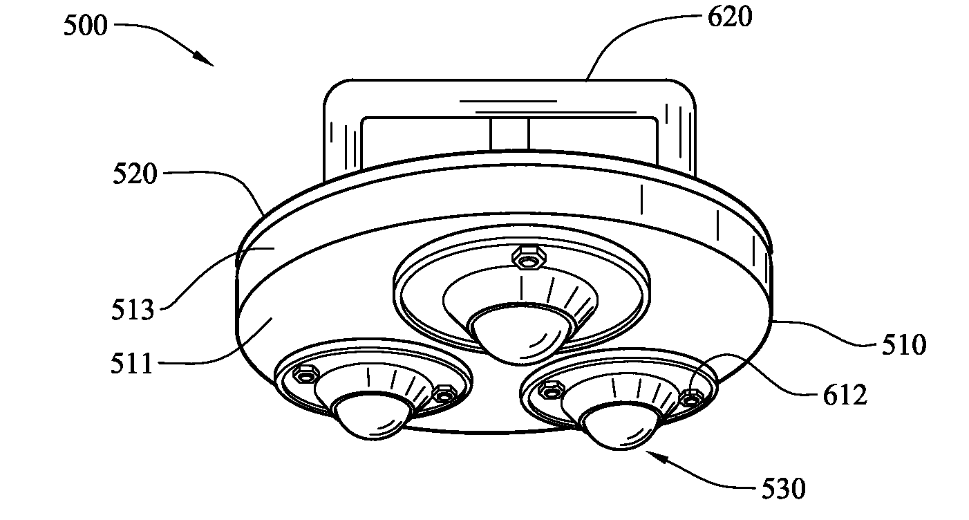
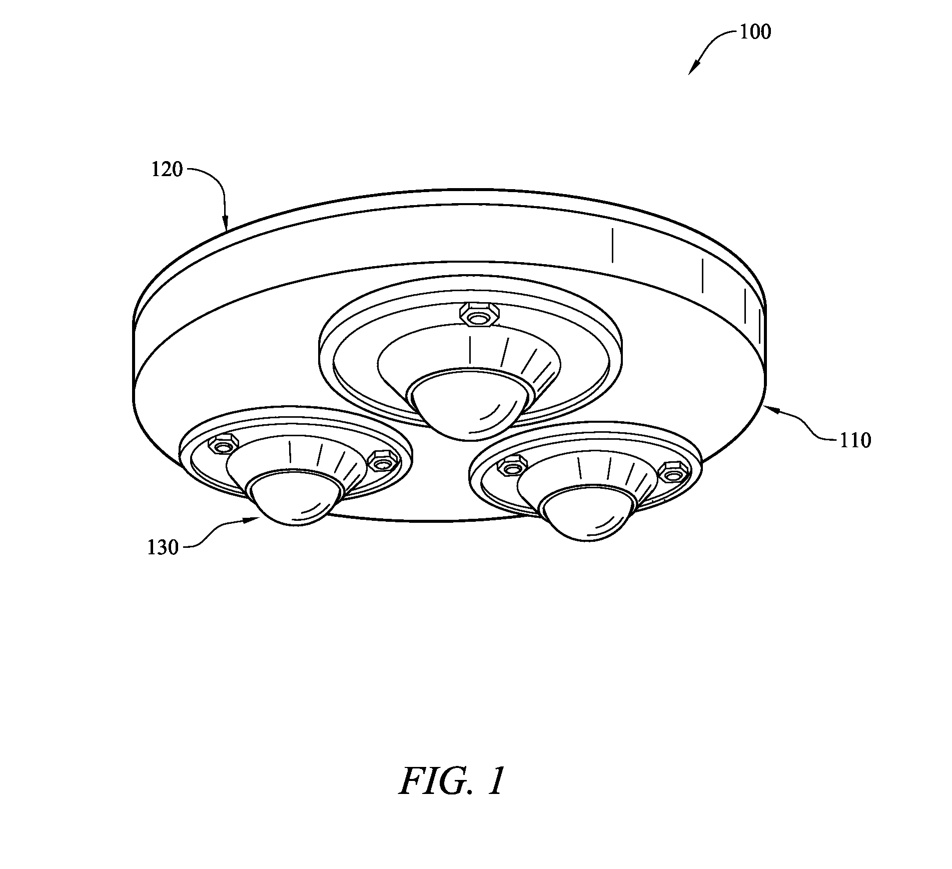
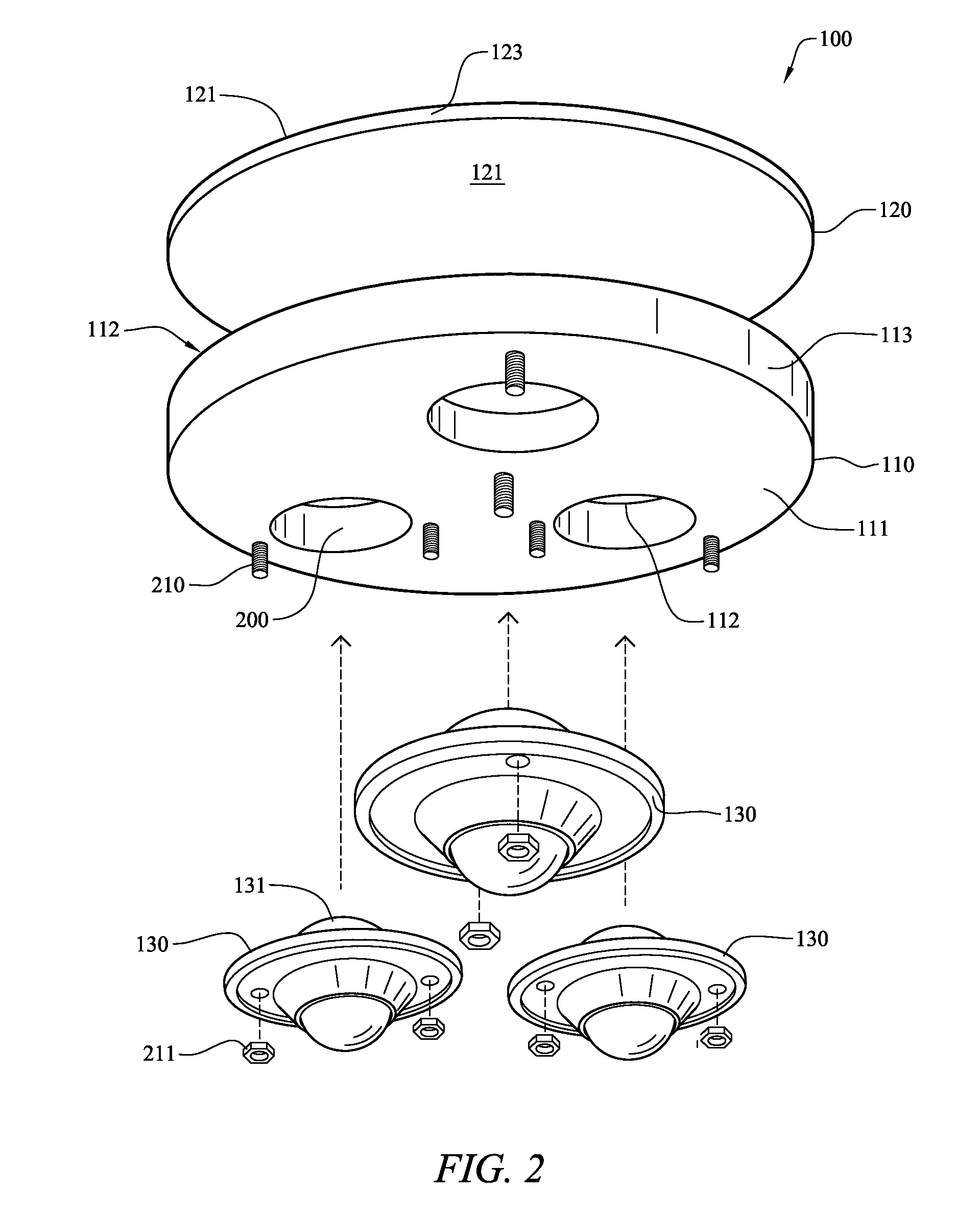
The patent describes an omnidirectional exercise platform that allows for full movement in multiple directions. It includes a base member with a top surface and bottom surface, and a pad member with a top surface, bottom surface, and sidewalls. The base member has multiple apertures in its bottom surface, which are coupled with ball transfer units to reduce rolling resistance when the platform is used on a support surface during physical training exercises. Overall, this invention provides a more effective and efficient tool for physical training.

Problems solved by technology

It is known that performing the same exercise over and over cause the human body to adapt to these exercise motions and thereby causing a diminishing return by performing the same exercise repeatedly.
While this known solution is somewhat useful, it presents substantial drawbacks.
Firstly, this device only permits the handle member to rotate which in turn allows the arms of a user to twist during the push-up.
Secondly, this device does not permit lateral motion of the device along the floor surface and thereby fails to activate many secondary muscle groups in the shoulders, chest, and back of a person during the exercise motion.
While this known solution is somewhat useful, it presents substantial drawbacks.
This additional force requirement induces an inconsistency in the exercise motion.
Further, this device does not facilitate a smooth uniform exercise motion because the multiple casters must realign prior to changing direction.
This configuration is likely to have increased axle friction under load and thus does not facilitate free motion.
Various exercise devices are known that employ a plurality of ball and cup-type members coupled to a bottom surface of the device and while somewhat useful these known solutions present substantial drawbacks.
These known solutions, while providing some benefit, have a substantial drawback of increased friction between the ball member and hemispherical cup under load conditions.
This type of ball motion assembly has a substantial portion of the ball member surface area in sliding contact with the surface area of the hemispherical cup and thereby restricts the free motion of the ball with respect to the cup under load.
Moreover, in these known solutions, as a user increases the load on the device the induced additional friction between the ball and cup prevent the fluid multi-directional movement of the exercise device.
While this known solution is somewhat useful, it presents substantial drawbacks.
Most significantly, this device only provides a single support ball, which causes the hemispherical support frame to be unstable during use.
However, the exercise device must provide a stable platform by which the exercise can be safely performed and which reduces the possibility of injuring the user.
Although this known exercise device provides a platform that facilitates fluid multi-directional movement during use, this device inherently presents an increased risk of potential injury to the user.
During use, this high center of rotation is likely to cause an undesired change in direction, due to the instability of the device, which may injure the hand, wrist, foot, or ankle of a user.
This horizontal freedom of movement causes a twisting / torquing of the wrist joint of the user, which in turn is likely to result in a significant and painful injury to the user.
As discussed above, this known solution presents a similar risk of injury to the ankle of the user, due to the horizontal freedom of movement, which can induce an undesired twisting / torquing of the ankle joint.
Efforts to provide an omnidirectional exercise platform that overcomes the drawbacks in the prior art have not met with significant success to date.

Method used


Image

  • Omnidirectional exercise platform
  • Omnidirectional exercise platform
  • Omnidirectional exercise platform

Examples


Embodiment Construction

[0025]The following detailed description is merely exemplary in nature and is not intended to limit the described embodiments or the application and uses of the described embodiments. As used herein, the word “exemplary” or “illustrative” means “serving as an example, instance, or illustration.” Any implementation described herein as “exemplary” or “illustrative” is not necessarily to be construed as preferred or advantageous over other implementations. All of the implementations described below are exemplary implementations provided to enable persons skilled in the art to make or use the embodiments of the disclosure and are not intended to limit the scope of the disclosure, which is defined by the claims. In other implementations, well-known features and methods have not been described in detail so as not to obscure the invention. For purposes of description herein, the terms “upper”, “lower”, “left”, “right”, “front”, “back”, “vertical”, “horizontal”, and derivatives thereof shal...


PUM


Abstract

An omnidirectional exercise platform is disclosed which includes a base member, a pad member and a plurality of ball transfer units. The pad member is coupled to a top surface of the base member. The plurality of ball transfer units is coupled to a bottom surface of the base member. An angular offset is provided between the plurality of ball transfer units to stabilize the omnidirectional exercise platform during use. The ball transfer units each comprise a hemispherical housing, a primary ball member and a plurality of secondary ball members disposed between an inner surface of the hemispherical housing and the primary ball member. The housing further includes an aperture located and sized to facilitate cleaning and maintenance procedures of the ball transfer unit. A handle is releasably coupled to the top surface of the base member to thereby provide a user with a variety of hand placement positions.

Description

FIELD OF THE INVENTION[0001]The present disclosure generally relates to exercise devices. More particularly, the present disclosure relates to an exercise platform that provides for omnidirectional movement of the platform while performing various exercises.BACKGROUND OF THE INVENTION[0002]Over the years physical exercise has grown in popularity to improve the health and physical appearance of a person and also to reduce stress. There are a many forms of physical exercise that may be employed by a person such as: strength training, aerobics, calisthenics, and plyometrics to name a few. A common strength training exercise is the traditional push-up. In performing a push-up, a user assumes a prone position, and lifts the body using the arms. Through this exercise, the weight of the body serves as the main source of resistance to the muscles, particularly the pectoralis muscles, which are used in performing the push-up. However, greater muscle training efficiency may be obtained by act...

Claims


Application Information

Patent Timeline
Patent Type & Authority Applications(United States)
IPC IPC(8): A63B21/00
CPCA63B21/0004A63B21/1469A63B23/1236A63B23/0205A63B23/0355A63B22/20A63B21/4035
Inventor NICHOLAS, PAUL JAMES
Owner OMNI EXERCISE
Learn More