Microwave oven with a waveguide including a reflector element

a technology of reflector element and microwave oven, which is applied in microwave heating, electric heating, electric/magnetic/electromagnetic heating, etc., to achieve the effect of enhancing the microwave distribution within the oven cavity, and being simple and inexpensiv

Active Publication Date: 2019-12-10
ELECTROLUX APPLIANCES
View PDF22 Cites 0 Cited by
  • Summary
  • Abstract
  • Description
  • Claims
  • Application Information

AI Technical Summary

Benefits of technology

[0006]It is an objective of embodiments of the invention to provide technically simple and inexpensive means for impedance matching between the microwave generator and the oven cavity and for enhancing the microwave distribution within the oven cavity. The objective is solved by the features of the independent claims. Preferred embodiments are given in the dependent claims. If not explicitly indicated otherwise, embodiments of the invention can be freely combined with each other.
[0007]According to a first aspect, a microwave oven is disclosed. The microwave oven comprises an oven cavity, a microwave generator for generating microwaves and a waveguide for guiding the microwaves to the oven cavity. The waveguide includes a reflector element comprising a plurality of reflection surfaces, the reflector element being fixedly arranged within the waveguide or integrated in the waveguide wall in order to reflect the microwaves into the oven cavity in a distributed manner. By means of the reflector element, a scattering of the microwaves is obtained thereby leading to a uniform microwave distribution within the oven cavity without any rotating elements. In addition, a means of impedance matching between the microwave generator and the oven cavity is achieved.
[0008]According to embodiments, the reflection surfaces are slanted with respect to the surface of the waveguide on which the reflector element is located. The reflection surfaces may be slanted by an angle between 0° and 90°, preferably between 0° and 60°, most preferably between 0° and 45° with respect to the surface of the waveguide on which the reflector element is located. Thereby, microwaves propagating through the waveguide are reflected out of the waveguide through an opening into the oven cavity. Even multiple reflections between the reflector element and the walls of the waveguide may be achieved thereby enhancing the microwave distribution within the oven cavity.

Problems solved by technology

A drawback of the known microwave ovens is that rotating elements driven by a motor are necessary in order to obtain uniform heating, respectively, avoid critical operation in case of a mismatched load.

Method used


Image

  • Microwave oven with a waveguide including a reflector element
  • Microwave oven with a waveguide including a reflector element

Examples


Embodiment Construction

[0027]The present invention will now be described more fully with reference to the accompanying drawings, in which example embodiments are shown. However, this invention should not be construed as limited to the embodiments set forth herein. Throughout the following description similar reference numerals have been used to denote similar elements, parts, items or features, when applicable.

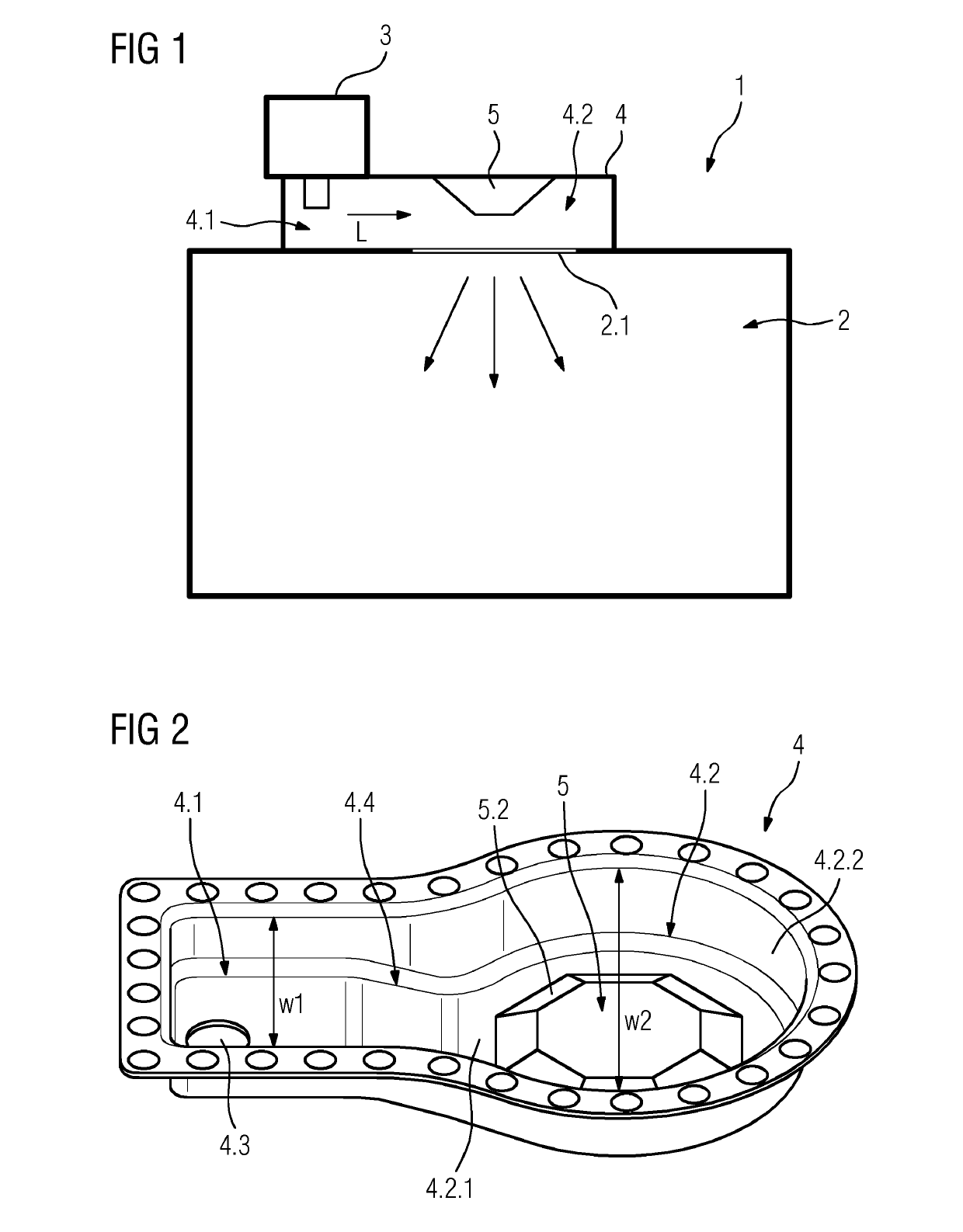
[0028]FIG. 1 shows a schematic diagram of a microwave oven 1. The microwave oven 1 comprises an oven cavity 2 adapted to receive food to be heated up, a microwave generator 3 adapted to generate microwaves (electromagnetic waves with a wavelength of 10 cm-40 cm) and a waveguide 4 for coupling the microwave generator 3 with the oven cavity 2. The waveguide 4 may be a rectangular waveguide or a launcher. The microwave generator 3 may be constituted by a magnetron.

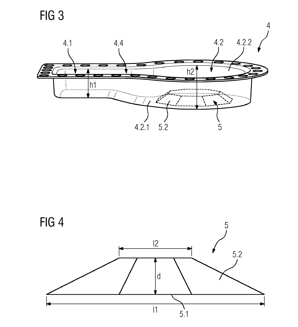
[0029]The waveguide 4 may comprise a feed-in area 4.1 at which the microwaves are coupled in. The microwaves generated by the microwave gene...


PUM


Abstract

The invention relates to a microwave oven comprising an oven cavity (2), a microwave generator (3) for generating microwaves and a waveguide (4) for guiding the microwaves to the oven cavity (2), wherein the waveguide (4) includes a reflector element (5) comprising a plurality of reflection surfaces (5.2), the reflector element (5) being fixedly arranged within the waveguide (4) or integrated in the waveguide wall in order to reflect the microwaves into the oven cavity (2) in a distributed manner.

Description

[0001]The present invention relates generally to the field of microwave ovens. More specifically, the present invention is related to an enhanced microwave distribution within microwave ovens.BACKGROUND OF THE INVENTION[0002]Microwave ovens for preparing food are well known in prior art. Typically, uniform energy distribution within microwave ovens is desired because the food to be prepared should be heated uniformly. In addition a maximized power transfer to the food to be prepared should be achieved thereby keeping the microwave generator of the microwave oven working in the allowed impedance region.[0003]Microwave ovens may comprise a turntable, on which the food to be prepared is located. By rotating the turntable, an evenly distributed heating of the food is obtained. Another type of microwave ovens comprises mode stirrers to achieve uniform heating. Said microwave ovens allow a variation of the working point of the microwave generator avoiding a critical operation in case of a...

Claims


Application Information

Patent Timeline
Patent Type & Authority Patents(United States)
IPC IPC(8): H05B6/70
CPCH05B6/707
Inventor MAZZON, CLAUDIO
Owner ELECTROLUX APPLIANCES
Why Eureka
Try Eureka