Method and device for adjusting a camera

a technology of camera and lens, applied in the field of camera adjustment, can solve the problems of insufficient recognition of image field, inability to adjust camera, and advanced technology of autofocus device, and achieve the effect of less sophisticated and advantages in practical us

Inactive Publication Date: 2006-03-28
VISION COMPONENTS FUR BILDVERARBEITUNGSSYST MBH
View PDF11 Cites 4 Cited by
  • Summary
  • Abstract
  • Description
  • Claims
  • Application Information

AI Technical Summary

Benefits of technology

[0011]Taking into account this state of the art, this invention has the object to provide a method and a device for the adjustment of a camera which is technically less sophisticated and which offers advantages in practical use.

Problems solved by technology

This method, however, has the disadvantage that the camera must be equipped with a sophisticated electronic system for generating the video signal required on site, and that the camera can only be adjusted if a connected monitor is available for this purpose.
This solution has the disadvantage that an autofocussing device is technically sophisticated, as the distance adjustment, in many application cases, does not have to be performed often, e.g. only during the initial set-up, or in case of maintenance and repair measures.
The viewfinder used for this has the disadvantage that the image field cannot be recognized sufficiently in many cases, in particular if the object width varies, and that the corresponding space conditions do not always allow to view the viewfinder with the human eye.
Adjustment and setting on site using the human eye is not possible here without using technical equipment for generating an image, captured by the image sensor for adjustment purposes.
A projection device for adjusting the image field is known from document U.S. Pat. No. 4,899,188, however, it does not solve the problem of the focusing of a reproduction device.
Thus, a sharpness control in not possible.

Method used


Image

  • Method and device for adjusting a camera
  • Method and device for adjusting a camera
  • Method and device for adjusting a camera

Examples


Embodiment Construction

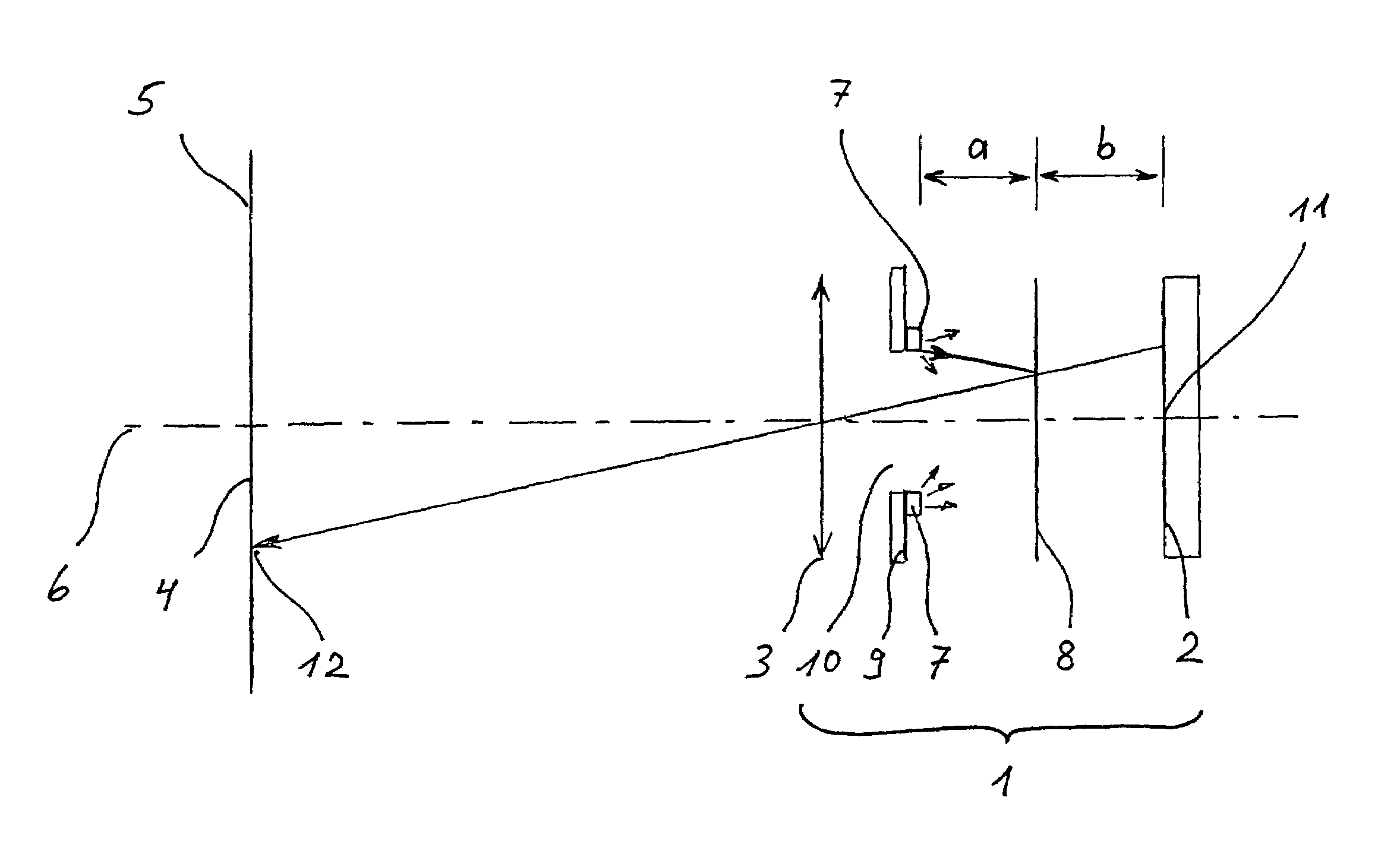
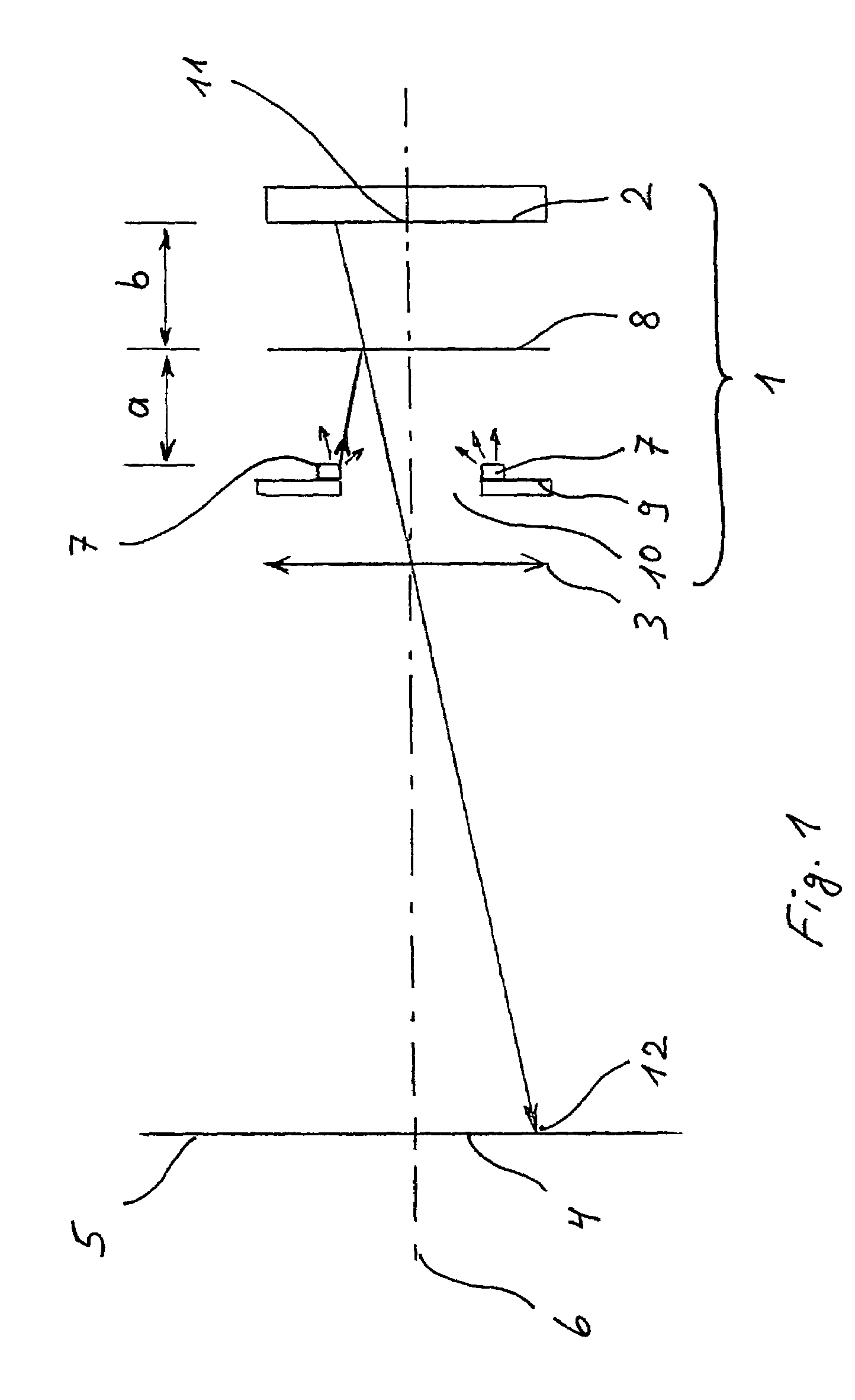
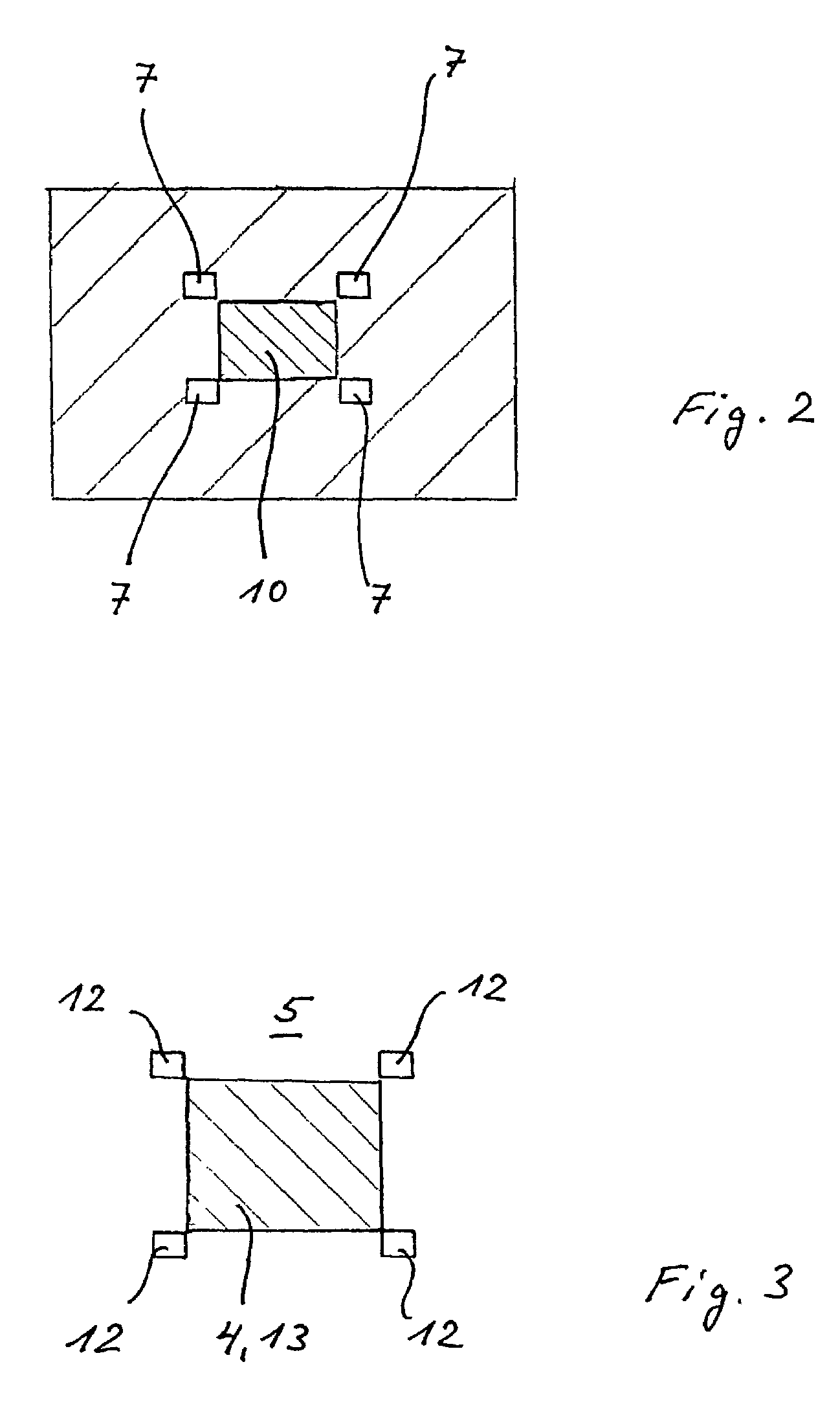
[0033]FIG. 1 shows the optical path and the design according to the invention. It comprises a camera 1 with an image sensor 2 and an objective 3 for imaging an object 4 onto the image sensor 2. The object 4 is located in the object plane 5, which can be, during the adjustment, e.g. a white piece of paper. The optic axis 6 is also shown in the optical path.

[0034]The image sensor 2 is, e.g. a unidimensional (line) or bidimensional (matrix) CCD sensor, a CMOS sensor or a photo diode array. All kind of image sensors, i.e. semiconductor sensors, in form of CCD line or CCD matrix, CMOS line or CMOS matrix, photo diode lines or photo diode arrays, camera tubes, CID lines or CID matrix, vidicons, newicons, plumbicons etc., as well as spread individual detectors, i.e. photo diodes, or positions-sensitive detectors, e.g. PSDs, can be considered here. For example, a Hewlett Packard / Agilent HDSC 2000 CMOS sensor can be used.

[0035]For the objective 3, arbitrary optical systems can be used, from ...


PUM


Abstract

For focussing and/or adjusting of the image field of a camera (1) with an image sensor (2) and an objective (3), it is proposed to provide light sources (7) between objective (3) and image sensor (2), which are projected into the object plane (5) by means of a partially transmitting mirror (8) arranged between the light sources (7) and the image sensor (2).

Description

BACKGROUND OF THE INVENTION[0001]This invention is related to a method and to a device for adjusting a camera with an image sensor for taking a picture and with an objective for imaging an object on the image sensor.[0002]During the use of cameras, for example in the scope of an industrial production for the monitoring, the control and the regulation of production procedures, it is necessary to adjust the camera. For this, the adjustment comprises the image sharpness setting of the optical imaging by appropriate corrective measures, as e.g. the change of the image width or object width of the optical imaging, or the adjustment of the objective, as well as the alignment of the position of the image field, which must correspond to the required visual field on the object, and which is adjusted by the position or by the alignment of the image sensor. These adjustment measures must be performed on the camera directly and on site.[0003]In case of camera systems with image sensors, a video...

Claims


Application Information

Patent Timeline
Patent Type & Authority Patents(United States)
IPC IPC(8): G03B13/00H04N5/222G02B7/28G02B7/32G03B13/36H04N5/225H04N5/232
CPCH04N5/2251H04N5/23212H04N5/2256H04N23/56H04N23/55H04N23/67
Inventor ENGEL, MICHAEL
Owner VISION COMPONENTS FUR BILDVERARBEITUNGSSYST MBH
Why Eureka
Try Eureka