
Brake Monitoring Device And Components Associated Therewith

Inactive Publication Date: 2013-10-03
HALDEX BRAKE PROD AB
View PDF20 Cites 6 Cited by
  • Summary
  • Abstract
  • Description
  • Claims
  • Application Information

AI Technical Summary

Benefits of technology

The objective of this patent is to create a simple brake monitoring system that works reliably and efficiently, is cost-effective and easy to install. The system should be effective in monitoring the brakes of a brake mechanism.

Problems solved by technology

Reasons for too large stroke could result from defective automatic slack adjusters, from a too large wear of the linings of the brake pads or brake shoes or from any other reasons.
A too short stroke may appear e.g. when the actuating cylinder does not work or when the brake is not properly released due to failing return mechanism.
Although, they prove to be rather cost effective, such monitoring devices need proper adjustment at installation and at overhaul, which in turn increases the costs.
However, such sensors prove to be too expensive when only excessive stroke shall be determined.
Also, such sensors are considered to be rather too expensive for simple tasks for monitoring the stroke.

Method used


Image

  • Brake Monitoring Device And Components Associated Therewith
  • Brake Monitoring Device And Components Associated Therewith
  • Brake Monitoring Device And Components Associated Therewith

Examples


Embodiment Construction

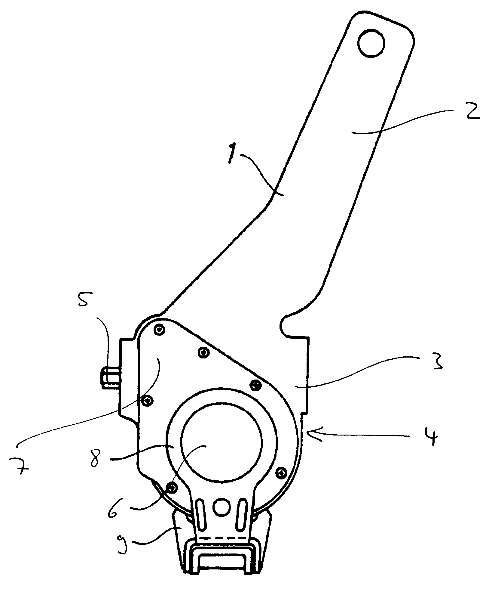
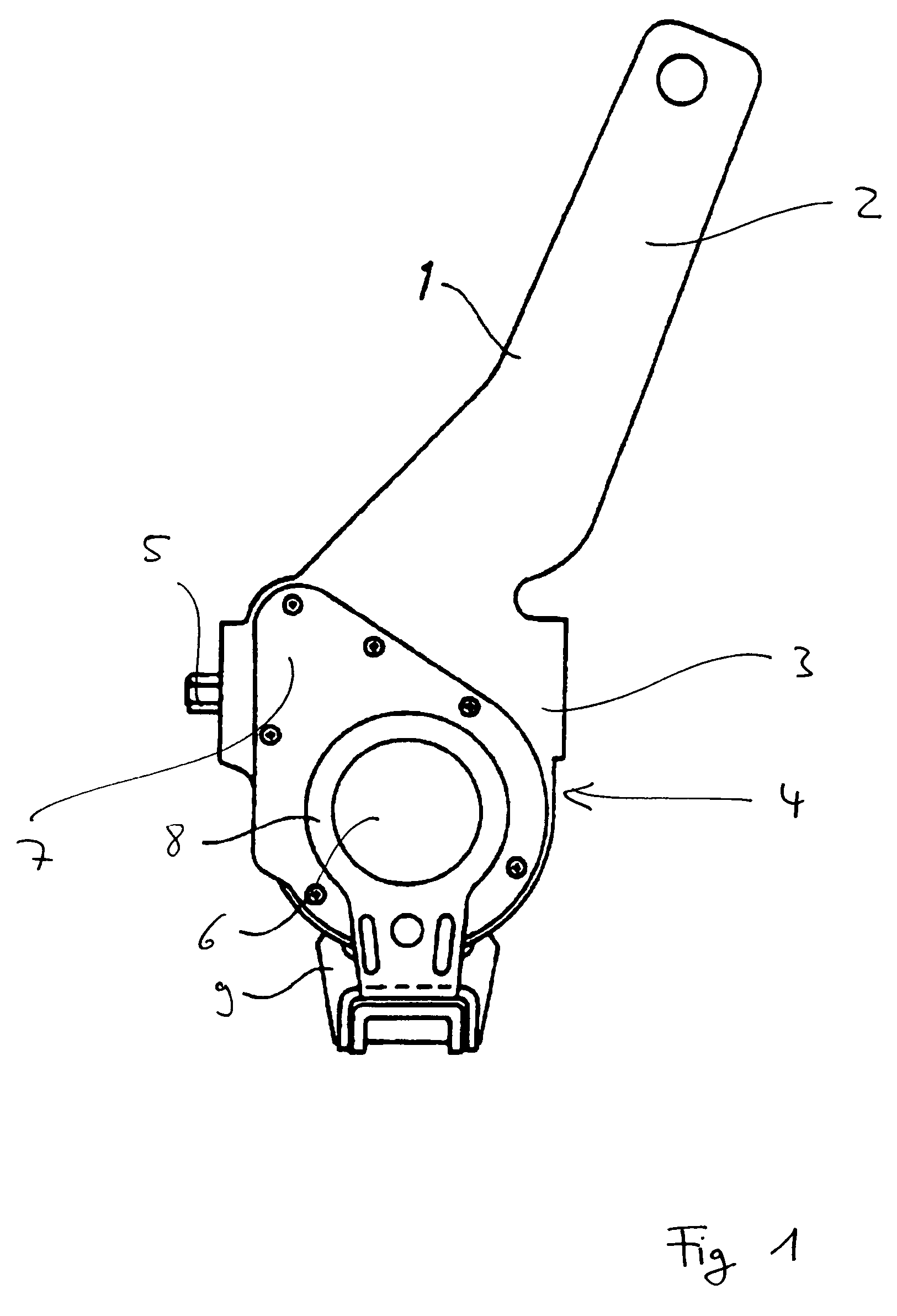
[0069]As an example, in FIG. 1 a self contained brake lever assembly for a drum brake is shown, as it is commonly used in the state of the art.

[0070]A lever 1 is made of cast iron and comprises an upper lever section 2 which attaches to a piston rod (not shown) of a hydraulic or pneumatic actuating cylinder. The upper lever section 2 descends into a lower lever section 3 with a housing 4 which receives an automatic slack adjuster mechanism 5 (partly shown by the end of a worm screw of said mechanism).

[0071]The slack adjuster mechanism 5 comprises, among other components, a worm screw and a worm wheel (not shown), the worm wheel being in connection with a S-cam shaft (not shown) via an opening 6 in the housing 4, as this is well known in the prior art. For further general information with respect to the configuration and function of such automatic slack adjusters it is e.g. referred to DE 195 34 854 A1 as previously mentioned.

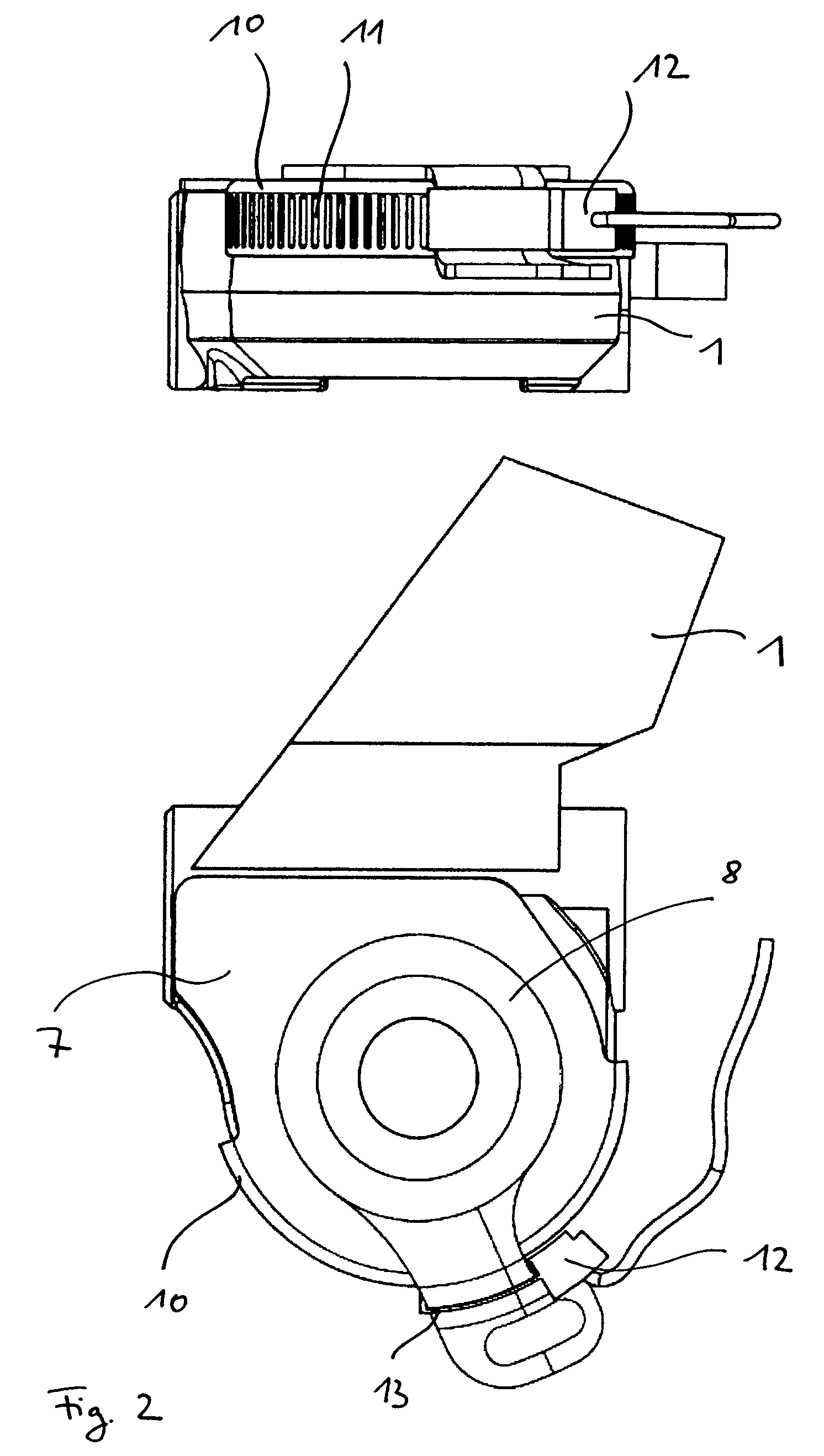
[0072]The housing 4 is closed at least on one of its sides...


PUM


Abstract

A monitoring device for detecting a value indicative of the actuation stroke and / or release stroke of a thrust element of a brake actuating mechanism, the thrust element being actuated by a lever of the brake actuating mechanism, including a sensor for sensing variations in a physical property of at least one part of the brake actuating mechanism, whereby the sensor and the part of the brake actuating mechanism are arranged so that by the relative movement between the part of the brake actuating mechanism and the sensor repeated variations in the physical property along a path of the relative movement are created and sensed. The path is formed between the lever and a stationary part being adjacent to the lever. The invention is directed both to drum brakes and to disc brakes.

Description

FIELD OF THE INVENTION[0001]The present invention refers to a brake monitoring device to be employed in brake mechanisms of different kind. Further, the invention refers to a drum brake and a disc brake, respectively, which comprise such a brake monitoring device. Several components of brake actuating mechanisms, which cooperate which such a brake monitoring device, are considered by this invention as well.BACKGROUND OF THE INVENTION[0002]In vehicle brakes, at least one rotor connected to a wheel is braked by friction elements to be applied to the rotor during brake actuation. In drum brakes, brake shoes are radially and tangentially moved towards the rotating drum, the brake shoes being arranged inside the drum and spread by means of a S-cam in fixed connection with a shaft, which shaft is set into rotation by a lever.[0003]In some kind of disc brakes a brake pad at the end of at least one thrust element is pushed towards the brake disc, the thrust element being actuated by a lever...

Claims


Application Information

Patent Timeline
IPC IPC(8): G01L5/28F16P1/00G05G1/04
CPCB60T7/042B60T7/085B60T17/22F16D2066/003F16P1/00Y10T74/20582G05G1/04F16D65/60F16D66/00Y10T74/219G01L5/28
Inventor SEGLO, FREDRIKLARSSON, ANDERS
Owner HALDEX BRAKE PROD AB
Learn More