
Energy system control

a technology of energy system and control panel, applied in the field of energy system control, can solve the problem of limit to the extent to which the accuracy of predictive modelling can be improved

Pending Publication Date: 2022-05-26
THE UNIV OF BIRMINGHAM
View PDF0 Cites 0 Cited by
  • Summary
  • Abstract
  • Description
  • Claims
  • Application Information

AI Technical Summary

Benefits of technology

The patent text describes a system for controlling energy storage and distribution in a way that compensates for any deficits or surplus in energy supply and demand. The system uses the power output of the energy storing system as a sensor to make real-time adjustments to the energy operators controllable by the controller. By controlling the energy storing system, the system can automatically compensate for any discrepancies between generation and demand. This allows for a self-correcting system that doesn't require excessive human intervention. The system can also use the energy storing system to adjust the supply and demand to prevent waste or reduce the need for a larger system. Overall, the technical effects of the patent text make it possible to achieve efficient and accurate control of the energy storage and distribution system.

Problems solved by technology

There are however natural limits to how much the accuracy of predictive modelling can be improved.

Method used


Image

  • Energy system control
  • Energy system control
  • Energy system control

Examples


Embodiment Construction

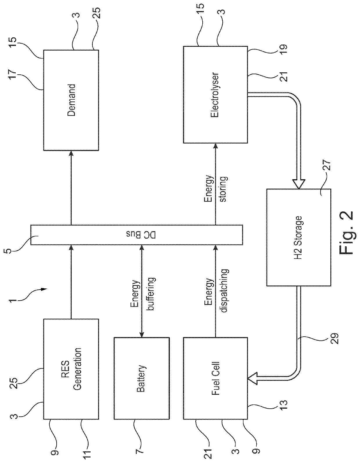
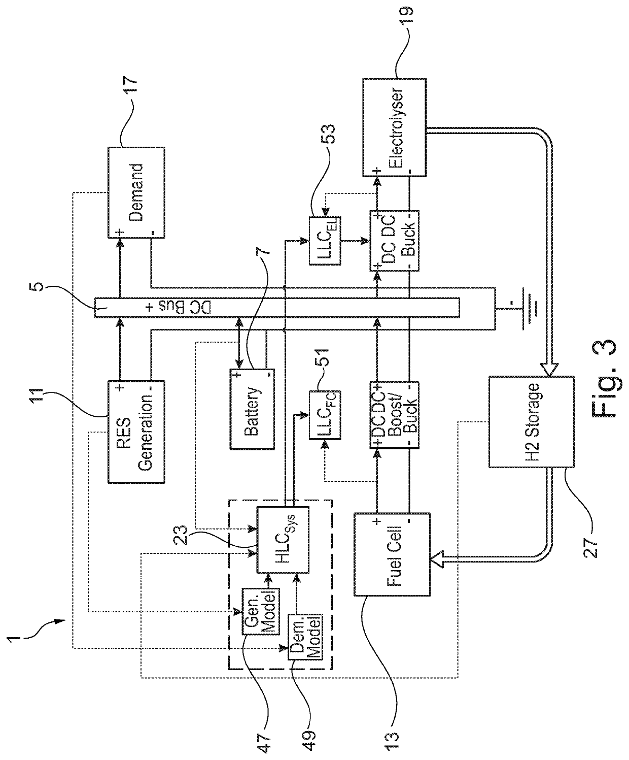
[0067]Referring first to FIGS. 2 and 3, an energy system is generally provided at 1. In this case the energy system 1 is an electrical energy system and has a number of energy operators 3, a common connection (in this case a busbar 5) and an energy storing system (in this case a battery 7).

[0068]Among the energy operators 3 are those which are energy supply systems 9 (in this case a renewable energy source 11 and a hydrogen fuel cell 13) and those which are energy consuming systems 15 (in this case an electrical demand 17 and an electrolyser 19). In this case, all of the energy operators 3 are variable energy operators, in that the electrical energy which they supply (in the case of energy supply systems 9) and consume (in the case of energy consuming systems 15) in a given time period is variable. Nonetheless, in other embodiments it will be appreciated that one or more of the energy operators 3 may be arranged to supply / demand a fixed quantity of electrical energy in a given time ...


PUM


Abstract

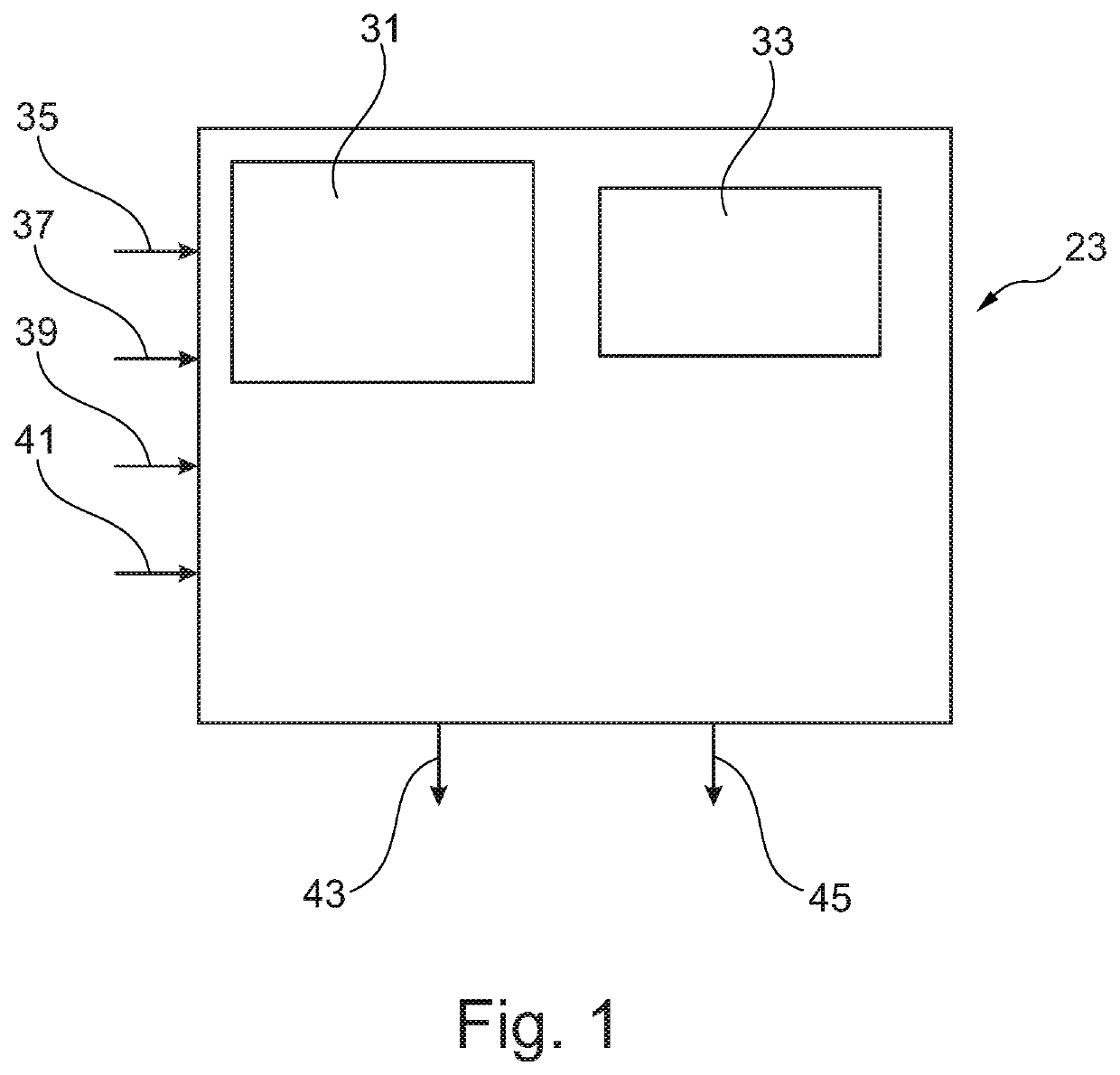
The disclosure concerns a controller arranged to control an energy system where the energy system comprises one or more first energy operators and one or more second energy operators, an energy storing system and an energy storing system monitoring device. The controller is arranged to have control over variation in operation of the one or more first energy operators and variation in operation of the second energy operators is at least partially beyond the control of the controller. At least one of the energy operators is an energy supply system and at least one and the remainder of the energy operators are energy consuming systems. At least two of the energy operators are variable energy operators. Where an energy supply system is a variable energy operator, variation in operation of that energy supply system adjusts the energy it supplies. Where an energy consuming system is a variable energy operator, variation in operation of that energy consuming system adjusts the energy it consumes. Outputs of the energy supply systems, inputs of the energy consuming systems and a connection of the energy storing system are connected by a common connection such that they are maintained at the same potential. The energy storing system is arranged to provide energy to the common connection to compensate where there is a deficit in energy supplied by the at least one energy supply system as compared with the energy demand from the at least one energy consuming system. The controller comprises an input arranged to receive a data signal indicative of the power output of the energy storing system from the energy storing system monitoring device; a processing system arranged to determine, in accordance with the energy storing system power output data received, whether and to what extent there is a deficit which exceeds an energy storing system discharging set point value, and where there is, a variation in control for at least one of the first energy operators corresponding in magnitude to the determined extent of the deficit to compensate and return the deficit to the energy storing system discharging set point value; and an output via which the processing system sends one or more control signals to control the at least one of the first energy operators accordingly.

Description

TECHNICAL FIELD[0001]The present disclosure concerns energy system control. More specifically the disclosure concerns a controller, an energy system, a method of controlling an energy system, a computer program, a non-transitory computer readable storage medium and a signal.BACKGROUND[0002]In circumstances where an energy system comprises multiple energy sources and / or multiple energy sinks where at least one of those is subject to fluctuations in its supply / demand beyond the control of the system, there is a need for compensation where mismatches in supply and demand occur as a result of the fluctuations. Compensation may be provided at least in part by adjusting operation of other sources and / or sinks within the system. Additionally, an energy store may be provided at least in part to compensate whilst any adjustments necessary to the sources and / or sinks are made.[0003]Providing responsive and accurate adjustments is significant because it allows for a reduction in the capacity o...

Claims


Application Information

Patent Timeline
IPC IPC(8): B60L58/40G05B15/02H02J15/00H02J3/14H02J3/32H02J7/00
CPCB60L58/40G05B15/02H02J15/008H02J3/144H02J2300/20H02J7/00032H02J7/0047H02J2300/30H02J3/32H02J3/28H02J2300/28Y04S20/222Y02B70/3225Y02T10/70
Inventor AL-SAGHEER, YOUSIFSTEINBERGER-WILKENS, ROBERT
Owner THE UNIV OF BIRMINGHAM
Learn More