Mounting plate and mounting plate system for a ski binding

a technology of mounting plate and ski binding, which is applied in the direction of skis, ski bindings, sports apparatus, etc., can solve the problems of having to be unscrewed and new ones screwed in place, affecting the properties, and the area designated for attaching the binding in this way has been limited or eliminated, and achieves the effect of simple and inexpensiv

Active Publication Date: 2021-03-02
ROTTEFELLA AS
View PDF22 Cites 0 Cited by
  • Summary
  • Abstract
  • Description
  • Claims
  • Application Information

AI Technical Summary

Benefits of technology

[0025]The mounting plate according to the invention permits use of the same mounting plate for different types of skiers and different types of binding systems. For fixed bindings, there will be no need for elements other than the mounting plate and a rail. Thus, the most basic solution can be made technically simple and inexpensive, whilst the mounting plate can be reused for more advanced solutions.
[0026]In addition to being adapted for different binding solutions, it is important that the mounting plate is extremely light, but at the same time robust, so that it can withstand the different loads to which it is subjected by different types of skiers with different binding combinations.

Problems solved by technology

If the bindings were damaged, or it was desirable to move the bindings, they had to be unscrewed and new ones screwed in place.
This can affect the properties of the ski, and for a number of skis where weight and flexibility are of crucial importance, the area designated for attaching bindings in this way has been limited or eliminated.
The binding and the heel plate can be adjusted slightly in the longitudinal direction during mounting, but the binding cannot be adjusted in the longitudinal direction without taking the skis off.
However, there is no easy way of reusing the mounting plate, such that the same plate and thus the ski can be used for both fixed bindings and bindings that can be moved in the longitudinal direction, where the fixed binding requires a minimum of extra components in addition to the mounting plate, such that this solution can be kept simple and inexpensive.

Method used


Image

  • Mounting plate and mounting plate system for a ski binding
  • Mounting plate and mounting plate system for a ski binding
  • Mounting plate and mounting plate system for a ski binding

Examples


embodiment 1

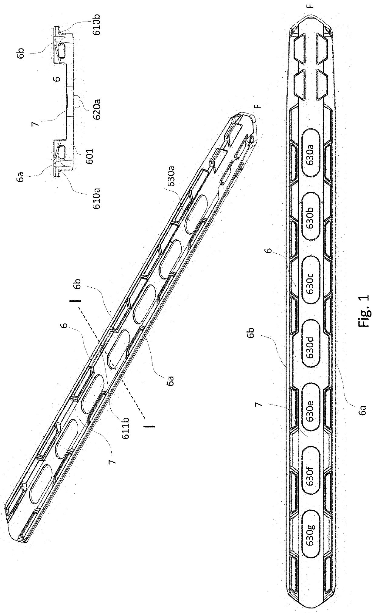
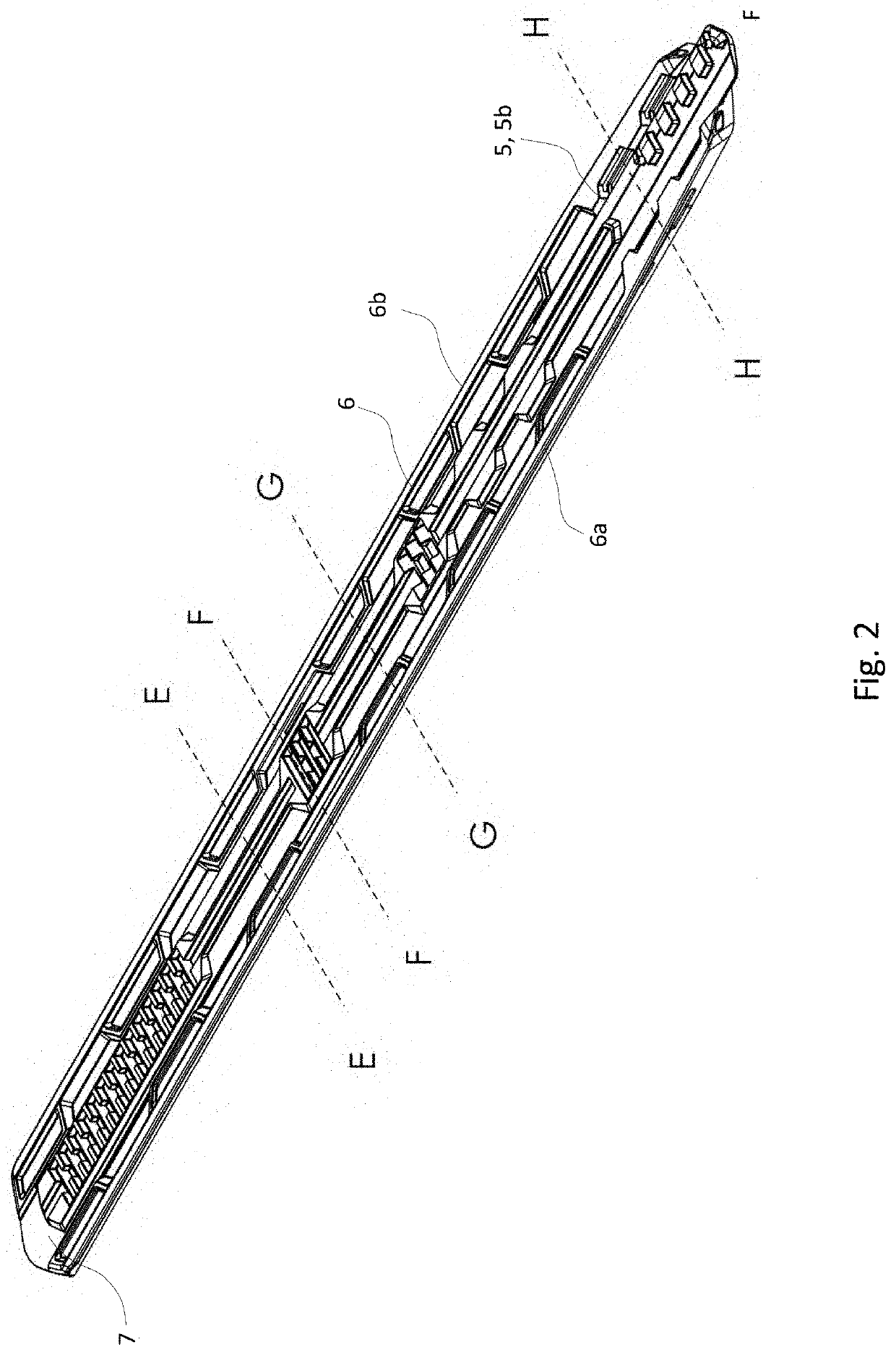
[0045]the mounting plate (1) according to the invention will now be explained with reference to FIGS. 1, 2, 3 and 4. In this embodiment, the mounting plate (6) comprises a bottom surface (601) configured to be laid against a ski. The ski is not shown.

[0046]The mounting plate (6) has an upward directed left and right side edge (6a, 6b) along the outer sides of the mounting plate, where the edges (6a, 6b) have laterally opposing undercuts (610a, 610b) that are configured to hold a ski binding (2a) with complementary cuts fastened to the mounting plate (6) in the vertical direction. Right and left side edges here are named in relation to a user's position on the ski, but what is right and left is not important in this connection.

[0047]The mounting plate (1) further comprises a longitudinal groove or channel (7).

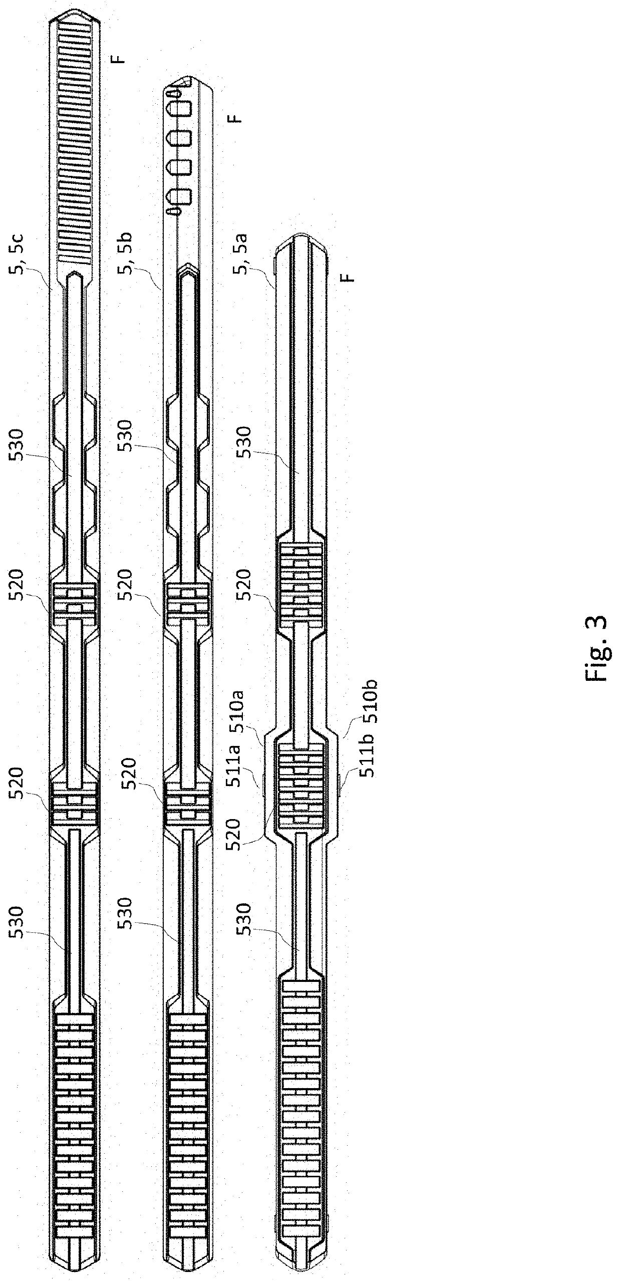
[0048]In an associated embodiment, the channel (7) is configured to hold a first interchangeable rail (5, 5a) fixed in the lateral direction and the longitudinal direction and a...

embodiment 3

[0056]In an embodiment 3, which can be combined with any one of the embodiments above, the mounting plate (6) comprises first and second guide pins (620a, 620b) which extend down from the bottom surface (601) and are arranged to be inserted into two holes in the ski, the first and the second pin (620a, 620b) having a different extent in the longitudinal direction.

[0057]Giving the pins a different extent in the longitudinal direction, e.g., in that one or more of the pins have an elongate form in the lateral direction corresponding to the diameter of the holes, allows at least some of the length variation that arises when the ski's binding portion is depressed to be taken up in that the elongate pin is able to migrate slightly in the longitudinal direction of the hole.

[0058]In an associated embodiment, the mounting plate (6) has a third guide pin (620c) which extends down from the bottom surface (601) and is arranged to be inserted into a hole in the ski, where the middle one (620b) ...

embodiment 4

[0060]In an embodiment 4, which can be combined with any one of the embodiments above, the height of the mounting plate (6) is greater at the forward part of the mounting plate (6) than at its central part.

[0061]In an associated embodiment, the height of the mounting plate (6) gradually increases towards the forward part of the mounting plate (6).

[0062]The rail will thus slide easily in the whole length of the groove, as the increase in thickness compensates for the curvature of the ski. By using an adjustment mechanism for the ski binding placed on the front of the plate, this effect will be even more obvious.

[0063]At the same time, the extra thickness in the tip will mean that the rail, which otherwise should be as thin and light as possible, obtains extra strength, such that the moving mechanism for the ski binding can be anchored in the area that has greatest strength. In addition to the actual improvement in the fastening of the moving mechanism, the forces from the moving mech...


PUM


Abstract

A mounting plate and mounting plate system for a ski comprising: a bottom surface configured to be placed against a ski; an upward directed left and right side edge along the outer sides of the mounting plate, where the edges have laterally opposed undercuts that are configured to hold a ski binding with complementary cuts fastened to the mounting plate in the vertical direction; a longitudinal groove, configured to hold a first interchangeable rail fixed in the lateral direction and the longitudinal direction, and a second interchangeable rail which can be interchanged with the first rail, fixed in a lateral direction but movable in the longitudinal direction.

Description

CROSS-REFERENCE TO RELATED APPLICATIONS[0001]This application is a national phase under 35 U.S.C. § 371 of PCT International Application No. PCT / NO2017 / 050303 which has an International filing date of Nov. 22, 2017, which claims priority to Norwegian Patent Application No. 20170170, filed Feb. 3, 2017, the entire contents of each of which are hereby incorporated by reference.TECHNICAL FIELD[0002]The present invention relates to a mounting plate and a mounting plate system for attaching a ski binding to a ski, where the same mounting plate can be used by skiers with different needs as regards binding solutions.BACKGROUND ART[0003]Ski bindings have throughout time been attached to skis in a number of different ways. Earlier, the most common was to screw the bindings in place in the skis. If the bindings were damaged, or it was desirable to move the bindings, they had to be unscrewed and new ones screwed in place. This can affect the properties of the ski, and for a number of skis wher...

Claims


Application Information

Patent Timeline
Patent Type & Authority Patents(United States)
IPC IPC(8): A63C9/00A63C9/086A63C9/20
CPCA63C9/086A63C9/003A63C9/005A63C9/0053A63C9/20A63C2009/008A63C5/128A63C9/00
Inventor ANDERSSEN, MAGNUSDANIELSEN, JORN FRODEGOVERUD-HOLM, THOMASSVENDSEN, OYVAR
Owner ROTTEFELLA AS
Why Eureka
Try Eureka