Screw and nut fastening device

a technology of screw and nut, which is applied in the direction of threaded fasteners, screw, liquid fuel engines, etc., can solve the problems of difficulty in corresponding machining, high cost, and inability to provide torque opposing the tightening or loosening torque exerted on the nut by some appropriate tool, wrench or automatic, etc., and achieves the effect of effectively preventing the movement of the fastening screw. simple and inexpensiv

Active Publication Date: 2008-05-06
SN DETUDE & DE CONSTR DE MOTEURS DAVIATION S N E C M A
View PDF29 Cites 4 Cited by
  • Summary
  • Abstract
  • Description
  • Claims
  • Application Information

AI Technical Summary

Benefits of technology

[0006]An object of the invention is to avoid the above-mentioned drawbacks and to provide a solution that is technically simple and inexpensive, for effectively preventing fastening screws from moving while two parts are being assembled together.

Problems solved by technology

To perform the operations of tightening and loosening a nut on a screw, it is necessary to prevent the screw from moving in rotation and in translation so as to ensure that it cannot turn freely, thereby failing to provide torque opposing the tightening or loosening torque exerted on the nut by some appropriate tool, such as, for example, a wrench or an automatic or semiautomatic screw-tightening machine.
Nevertheless, because of the particular shape and the dimensional and positioning tolerances on the recesses, the corresponding machining is difficult and expensive to perform, particularly when the part in question is bulky, and of complex shape requiring very great precautions to be taken during handling or while performing machining operations.
In addition, when the mechanical stress is applied to the part, the recesses can lead to stresses becoming concentrated within the part, thereby weakening it.
To increase the strength of the part in the vicinity of such recesses, and thereby increase its lifetime, it is common to reinforce the part by adding material around the recesses, thereby ending up with an increase in the weight of the assembly.
This extra weight can become a non-negligible drawback, for example in the field of aviation where it is desirable to reduce the weight of all on-board parts, or where the part is a moving part, e.g. an element of a turbocompressor or turbojet rotor, in which case it is desirable to reduce its inertia.
Another drawback of such recesses for preventing screw heads from moving is that their walls are subjected directly to the tightening torque exerted on the nut, and if that should exceed a predetermined limiting value, that can mark or even damage the part in which the recesses are formed.

Method used


Image

  • Screw and nut fastening device
  • Screw and nut fastening device
  • Screw and nut fastening device

Examples


Embodiment Construction

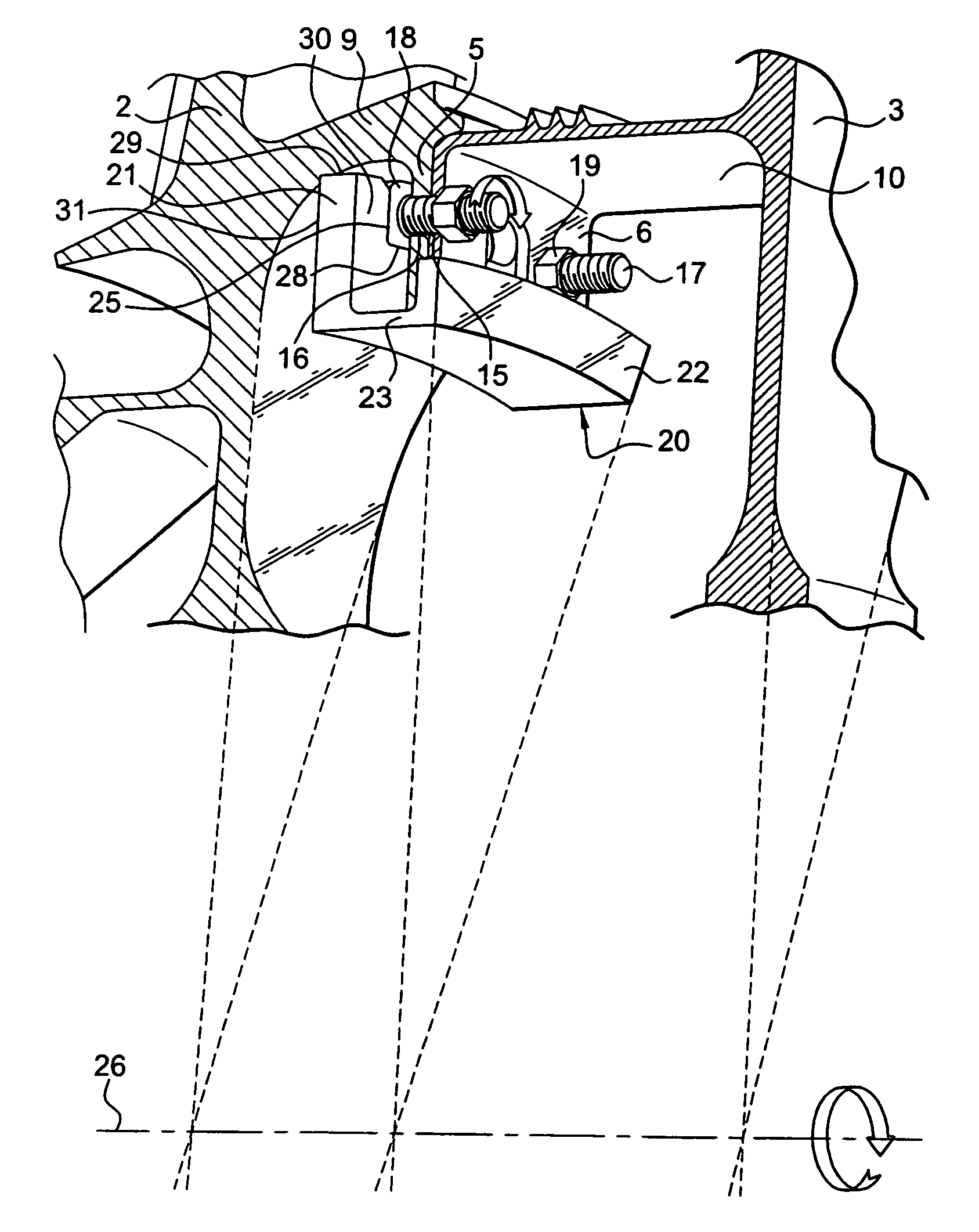
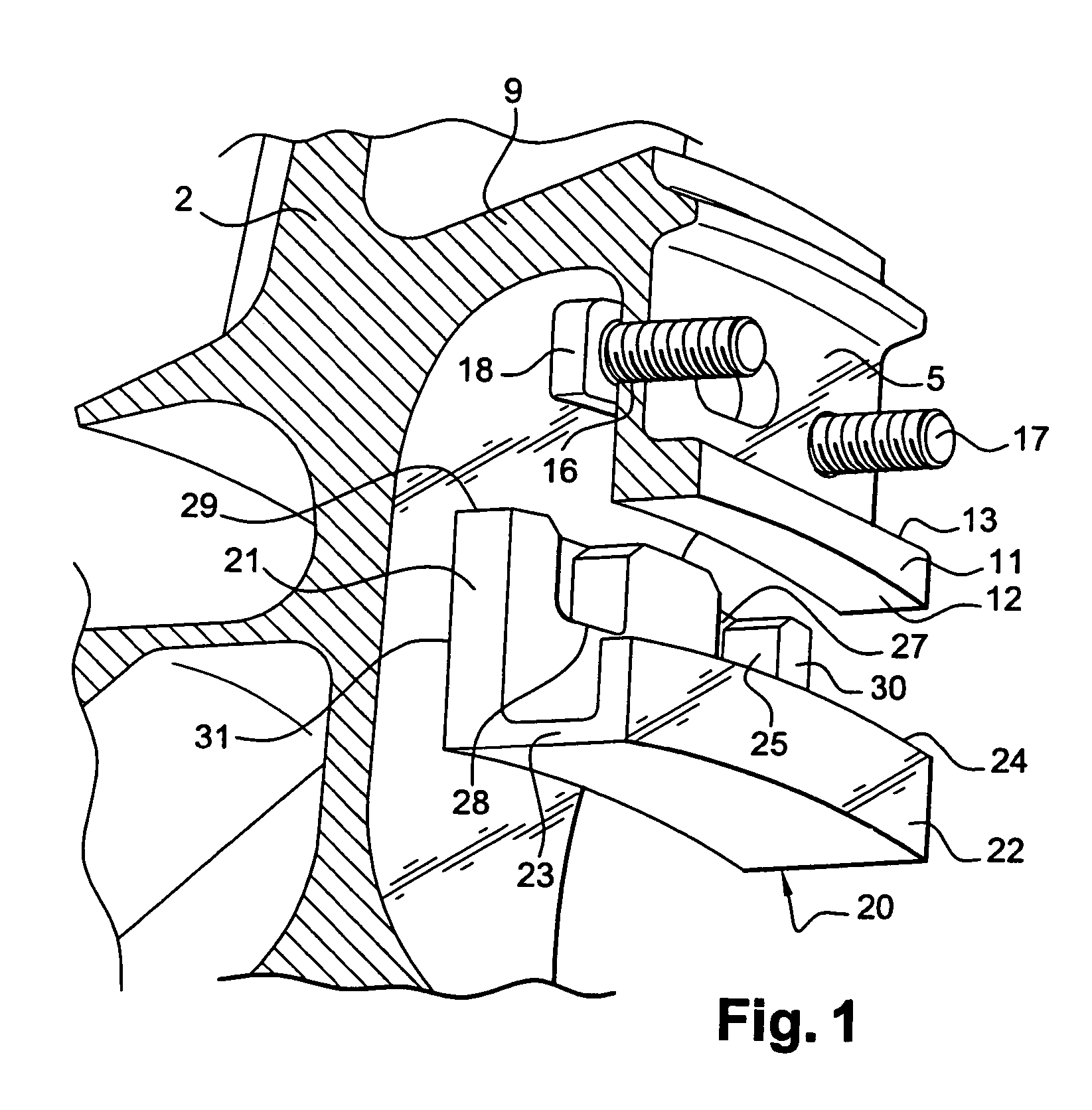
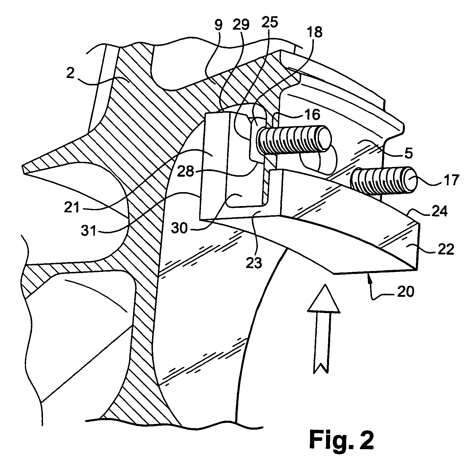
[0029]The device of the invention in this example is used to assemble together two annular parts 2 and 3 of a rotor of a turbocompressor. The first of these parts is a rotor disk 2 and the second is an annular part forming a spacer 3 and including in particular collars 4 for co-operating with stator vanes (not shown) so as to form a baffle seal. The two annular elements 2 and 3 are placed axially end to end and comprise respectively an annular flange 5 and flange-connection tabs 6 (see FIGS. 3 and 4) that extend radially inwards. A cylindrical wall 9 carrying the annular flange 5 extends from the rotor disk 2 around the axis 26 (FIG. 3), and a cylindrical wall 10 carrying the tabs 6 extends from the spacer part 3. Although FIGS. 1 to 4 show only an annular sector of the two annular parts 2, 3, the tabs 6 are regularly distributed around the entire radially inner periphery of the cylindrical wall 10. An annular rim 11 (FIGS. 1 and 4) is formed on the radially inner periphery 12 of th...


PUM


Abstract

A device for fastening two parts to each other includes fastening screws extending in aligned passages in the two parts and receiving nuts, and a removable element for preventing the screw heads from moving during tightening or loosening of the nuts on the screws, this removable element cooperating with one of the two parts for preventing rotation of the screw heads relative to this part.

Description

[0001]The present invention relates to a device for using screws and nuts to fasten two parts to each other.BACKGROUND OF THE INVENTION[0002]Such screw-and-nut fastening devices serve in particular to assemble together two or more separable parts, and they are very widespread in a variety of applications in all technical fields. To perform the operations of tightening and loosening a nut on a screw, it is necessary to prevent the screw from moving in rotation and in translation so as to ensure that it cannot turn freely, thereby failing to provide torque opposing the tightening or loosening torque exerted on the nut by some appropriate tool, such as, for example, a wrench or an automatic or semiautomatic screw-tightening machine.[0003]When such devices are used for assembling together annular elements of a turbomachine rotor, a solution described in documents FR-A-2 502 690 and FR-A-2 715 975 consists in preventing the screws from moving in rotation and in translation by providing h...

Claims


Application Information

Patent Timeline
Patent Type & Authority Patents(United States)
IPC IPC(8): F16B39/02F16B39/10F01D25/00F02C7/00F04D29/32F16B5/02F16B35/04
CPCF04D19/02F04D29/053F16B39/101F04D29/644F04D29/321F01D5/066F01D11/001Y02T50/60
Inventor DAO, DANIELLANDRAGIN, ERICGARCIN, FRANCOIS
Owner SN DETUDE & DE CONSTR DE MOTEURS DAVIATION S N E C M A
Why Eureka
Try Eureka