Seating assembly with thermoelectric devices

a technology of thermoelectric devices and seat assemblies, which is applied in the direction of seat heating/ventilation devices, vehicle components, vehicle arrangements, etc., can solve the problem that current solutions for providing cooled and heated surfaces can take extended periods of time to reach an occupant-perceptible temperature, and achieve the effect of increasing the efficiency of the thermoelectric devi

Active Publication Date: 2019-12-17
FORD GLOBAL TECH LLC
View PDF55 Cites 5 Cited by
  • Summary
  • Abstract
  • Description
  • Claims
  • Application Information

AI Technical Summary

Benefits of technology

[0018]According to another aspect of the present disclosure, a seating assembly includes a seating surface extending over at least one of a seat and a seatback. The seating assembly also includes a fluid mover and a seat trim proximate the seating surface. A fluid transfer member integral to the seat trim includes a gallery wherein the gallery has an inlet and an outlet and wherein the inlet is coupled to the fluid mover and the outlet is proximate a thermoelectric device. The thermoelectric device is arranged proximate the seating surface to heat or cool an occupant. The fluid mover is selectively operable to direct fluid away from the seating surface to increase an efficiency of the thermoelectric device.

Problems solved by technology

However, current solutions for providing cooled and heated surfaces can take extended periods of time to reach an occupant-perceptible temperature.

Method used


Image

  • Seating assembly with thermoelectric devices
  • Seating assembly with thermoelectric devices
  • Seating assembly with thermoelectric devices

Examples


Embodiment Construction

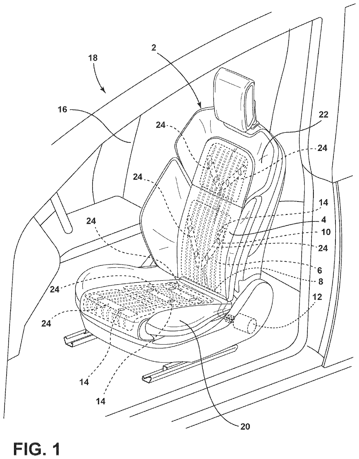
[0043]For purposes of description herein, the terms “upper,”“lower,”“right,”“left,”“rear,”“front,”“vertical,”“horizontal,” and derivatives thereof shall relate to the disclosure as oriented in FIG. 1. However, it is to be understood that the disclosure may assume various alternative orientations, except where expressly specified to the contrary. It is also to be understood that the specific devices and processes illustrated in the attached drawings, and described in the following specification are simply exemplary aspects of the inventive concepts defined in the appended claims. Hence, specific dimensions and other physical characteristics relating to the aspects disclosed herein are not to be considered as limiting, unless the claims expressly state otherwise.

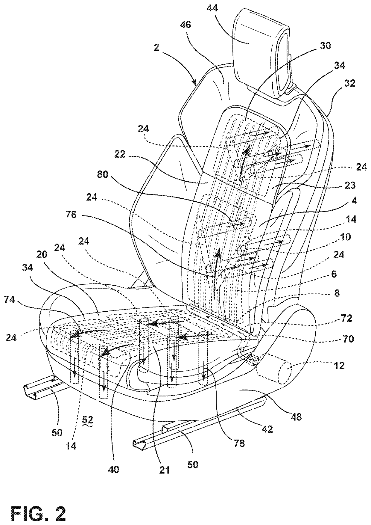
[0044]Referring to FIGS. 1-14, a vehicle seating assembly 2 includes a seating surface 4 and a tube 6 arranged proximate the seating surface 4. The tube 6 has an inlet 8 fluidly coupled with a fluid mover 12 and an outlet 10 p...


PUM


Abstract

A vehicle seating assembly includes a seating surface and a tube arranged proximate the seating surface. The tube has an inlet fluidly coupled with a fluid mover and an outlet proximate the seating surface. A thermoelectric device is in communication with the outlet. The thermoelectric device is configured to thermodynamically affect heat exchange at the seating surface. The fluid mover is selectively operable to release a pressurized fluid through the tube proximate the thermoelectric device.

Description

FIELD OF THE DISCLOSURE[0001]The present disclosure generally relates to a vehicle seating assembly, and more particularly to a climate controlled vehicle seating assembly.BACKGROUND OF THE DISCLOSURE[0002]Vehicle seat comfort has become increasingly important as passengers take longer trips. Providing cooling and heating in the seat can increase comfort of passengers.[0003]A variety of vehicle seating assemblies that provide for occupant cooling and heating are known. However, current solutions for providing cooled and heated surfaces can take extended periods of time to reach an occupant-perceptible temperature.SUMMARY OF THE DISCLOSURE[0004]According to one aspect of the present disclosure, a vehicle seating assembly includes a seating surface, and a tube arranged proximate the seating surface. The tube has an inlet fluidly coupled with a fluid mover and an outlet proximate the seating surface. A thermoelectric device is in communication with the outlet and configured to thermody...

Claims


Application Information

Patent Timeline
Patent Type & Authority Patents(United States)
IPC IPC(8): B60N2/56
CPCB60N2/5642B60N2/5635B60N2/5657B60N2/565B60N2/5678
Inventor DRY, ALAN GEORGEKONDRAD, MARCOS SILVAPREUSS, KEVIN WAYNEHOERNKE, SPENCER ROBERTLINE, JOHNATHAN ANDREW
Owner FORD GLOBAL TECH LLC
Why Eureka
Try Eureka