
Small-size heat pump drying device realizing high-efficiency dehumidification

A drying device, dehumidification heat technology, applied in heating device, drying gas arrangement, drying and other directions, can solve the problems of improving the inlet air temperature, and achieve the effect of increasing the outlet air temperature and great flexibility

Pending Publication Date: 2019-12-20
GUANGDONG UNIV OF TECH +1
View PDF0 Cites 2 Cited by
  • Summary
  • Abstract
  • Description
  • Claims
  • Application Information

AI Technical Summary

Problems solved by technology

However, the existing heat pump drying equipment does not improve the inlet air temperature.

Method used


Image

  • Small-size heat pump drying device realizing high-efficiency dehumidification

Examples


Embodiment

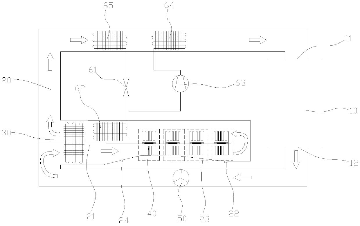
[0019] Please refer to figure 1 , A small and high-efficiency dehumidification heat pump drying device, including a sealed drying chamber 10, a heat pipe heat exchanger 30, a thermoelectric module 40 and a heat pump. The heat pump includes an expansion valve 61, an evaporator 62, and a compressor connected by pipes to form a loop. 63. The first condenser 64 and the second condenser 65, the evaporator 62, the first condenser 64 and the second condenser 65 are respectively finned heat exchangers;

[0020] The drying chamber 10 is provided with an air inlet 11 and an air outlet 12. The air inlet 11 and the air outlet 12 are connected by a drying channel 20, and the drying channel 20 is provided with a circulation that blows air from the air outlet side to the air inlet side. Fan 50;

[0021] The evaporator 62 is arranged on the side of the drying channel 20 close to the air outlet 12, and the first condenser 64 and the second condenser 65 are arranged on the side of the drying channe...


PUM


Abstract

The invention discloses a small-size heat pump drying device realizing high-efficiency dehumidification. The device comprises a sealed drying chamber, a heat pipe heat exchanger, a thermoelectric module and a heat pump, wherein the heat pump comprises an expansion valve, an evaporator, a compressor, a first condenser and a second condenser which sequentially communicate with one another through apipeline so as to form a loop; the drying chamber is provided with an air inlet and an air outlet, wherein the air inlet and the air outlet mutually communicate through a drying channel, and a circulating fan is arranged in the drying channel; the evaporator is arranged in the portion, close to one side of the air outlet, in the drying channel, and the first condenser and the second condenser arearranged in the portion, close to one side of the air inlet, in the drying channel; a baffling plate is arranged in the drying channel, a heat pipe heat exchanger evaporation section, a thermoelectricmodule cold end, a thermoelectric module hot end and a heat pipe heat exchanger condensing section are arranged sequentially in the air advancing direction, and the evaporator is arranged between thethermoelectric module hot end and the heat pipe heat exchanger condensing section; and the drying channel is provided with a drainage port below the thermoelectric module cold end. According to the small-size heat pump drying device realizing high-efficiency dehumidification, air is dehumidify, the relative humidity of the air is reduced, and therefore the purpose of high-efficiency dehumidifyingand drying can be realized.

Description

Technical field [0001] The invention relates to the technical field of drying equipment, and in particular to a small-sized high-efficiency dehumidification heat pump drying device. Background technique [0002] Drying has been widely used in food, fruit, wood, aquatic products, etc. The traditional drying method has problems such as lower efficiency, higher energy consumption and environmental pollution. Compared with other drying methods, heat pump drying has obvious advantages such as: environmental protection, high efficiency and energy saving, high thermal efficiency, fast dehumidification, and good quality and color of the dried items. However, the drying process is an extremely complex process, which involves a very complicated heat and mass transfer mechanism, and may even involve a certain biochemical reaction process. The drying rate of the heat pump mainly depends on the inlet air temperature of the drying chamber. The higher the inlet air temperature, the faster the ...

Claims


Application Information

Patent Timeline
Patent Type & Authority Applications(China)
IPC IPC(8): F26B21/00F26B23/00
CPCF26B21/001F26B23/005
Inventor 王长宏陈承戴王兴辉汤恩柱刘良德
Owner GUANGDONG UNIV OF TECH
Learn More