Air conditioner system

A technology for air conditioning systems and evaporators, which can be used in high-efficiency regulation technology, lighting and heating equipment, and irreversible-cycle compressors, etc. It can solve the problems of lower evaporation temperature, increase in input force, and increase in pressure ratio, and improve comfort. , the effect of moderate air temperature

Inactive Publication Date: 2017-06-23
SHANGHAI HITACHI ELECTRICAL APPLIANCES CO LTD
View PDF7 Cites 4 Cited by
  • Summary
  • Abstract
  • Description
  • Claims
  • Application Information

AI Technical Summary

Problems solved by technology

Often in order to achieve the purpose of dehumidification, the evaporation temperature should be reduced as much as possible. For the compressor, the pressure ratio increases, the input force increases, and the operation is uneconomical.
At the same time, in order to achieve the lower evaporation temperature of the system for dehumidification, the temperature of the indoor air outlet is lower, and the comfort of the human body is poor.

Method used


Image

  • Air conditioner system
  • Air conditioner system

Examples


no. 1 example

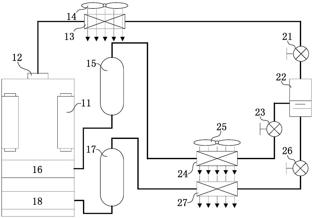
[0042] figure 1 It is a connection schematic diagram of the air conditioning system according to the first embodiment of the present invention. Such as figure 1 Shown, a kind of air conditioning system of the present invention, a compressor 11, a condenser 13, a first fan 14, a first electronic expansion valve 21, a flasher 22, the first pipeline and the second pipeline . The compressor 11 has a first compression chamber 16 and a second compression chamber 18. The exhaust port 12 of the compressor 11 is connected in series with a condenser 13, a first electronic expansion valve 21 and a flasher 22. The first electronic The expansion valve 21 throttles the refrigerant for the first time, and the flasher 22 has an exhaust port and a liquid discharge port. The air duct of the first fan 14 passes through the condenser 13 .

[0043] The first end of the first pipeline is connected to the exhaust port of the flasher 22, and the second end is connected to the first compression ch...

specific Embodiment approach

[0048] The exhaust gas of the compressor 11 of the present invention enters the condenser 13 , enters the first electronic expansion valve 21 for throttling once, and then enters the flasher 22 . The refrigerant liquid in the flasher 22 is stored at the bottom, and the flashed gas is placed at the top. The main function is to ensure that the liquid refrigerant is stable before throttling, has sufficient subcooling, and improves heat exchange efficiency. The outlet of the flasher 22 is divided into two paths. The gaseous refrigerant returns to the first compression chamber 16 from the top exhaust port through a first pipeline; the liquid refrigerant passes through a second pipeline from the bottom liquid discharge port. Back to the second compression chamber 18. The main refrigerant in the gaseous state of the flasher enters the first evaporator 24 (sensible heat evaporator) after being throttled twice; the main refrigerant in the liquid state of the flasher enters the second e...

no. 2 example

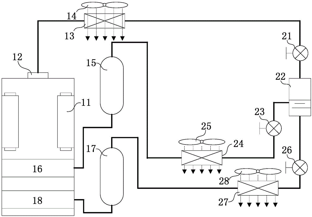
[0051] figure 2 It is a connection schematic diagram of the air conditioning system according to the second embodiment of the present invention. Such as figure 2Shown, another kind of air-conditioning system of the present invention is the same as the first embodiment, a kind of air-conditioning system of the present invention, a compressor 11, a condenser 13, a first fan 14, a first electronic expansion Valve 21, a flasher 22, first pipeline and second pipeline. The compressor 11 has a first compression chamber 16 and a second compression chamber 18. The exhaust port 12 of the compressor 11 is connected in series with a condenser 13, a first electronic expansion valve 21 and a flasher 22. The first electronic The expansion valve 21 throttles the refrigerant for the first time, and the flasher 22 has an exhaust port and a liquid discharge port. The air duct of the first fan 14 passes through the condenser 13 .

[0052] The first end of the first pipeline is connected to ...


PUM


Abstract

The invention provides an air conditioner system. The air conditioner system comprises a compressor, a first pipeline and a second pipeline, a first compressing cavity and a second compressing cavity are formed in the compressor, and an air outlet of the compressor is sequentially connected with a condenser, a first electronic expansion valve and a flash vaporization device in series; and the first end of the first pipe line is connected with an air outlet of the flash vaporization device, the second end of the first pipeline is connected with the first compressing cavity of the compressor, and the first pipeline comprises a second expansion valve, a first evaporator and a first liquid accumulator which are sequentially connected in series; and one end of the second pipeline is connected with a liquid outlet of the flash vaporization device, the second end of the second pipeline is connected with the second compressing cavity of the compressor, and the second pipeline comprises a third expansion valve, a second evaporator and a second liquid accumulator which are sequentially connected in series, and the evaporating temperature of the first evaporator is higher than that of the second evaporator. According to the air conditioner system, one of the evaporators can be maintained to operate at a high evaporating temperature for a long time, and the heating energy efficiency ratio of overall operation of the system can be increased.

Description

technical field [0001] The invention relates to an air conditioning system, in particular to an air conditioning system with two evaporation temperatures. Background technique [0002] At present, the method of humid air condensation dehumidification is used to remove indoor residual humidity. The surface temperature of the evaporator needs to be lower than the dew point temperature of the indoor air. Considering the temperature difference between heat transfer and medium delivery, for example, to achieve a dew point temperature of 16.6°C requires an evaporation temperature below 7°C. . Often in order to achieve the purpose of dehumidification, the evaporation temperature should be reduced as much as possible. For the compressor, the pressure ratio increases, the input force increases, and the operation is uneconomical. At the same time, in order to achieve the lower evaporation temperature for the purpose of dehumidification, the system makes the indoor air outlet temperat...

Claims


Application Information

Patent Timeline
Patent Type & Authority Applications(China)
IPC IPC(8): F25B1/10F25B41/06F25B41/31F25B41/34
CPCF25B1/10F25B41/31Y02B30/70
Inventor 张蕾张海锋傅海莹
Owner SHANGHAI HITACHI ELECTRICAL APPLIANCES CO LTD
Why Eureka
Try Eureka