

Dew-removing cooling switching power supply
A switching power supply and dew-collecting technology, which is applied in the modification of electrical components and power electronics, cooling/ventilation/heating transformation, etc., can solve the problem of switching power supply being damp, etc., and achieve the effect of improving heat dissipation, increasing heat dissipation effect, and low cost
Inactive Publication Date: 2017-12-15
CHONGQING LUGE TECH CO LTD
View PDF6 Cites 3 Cited by
- Summary
- Abstract
- Description
- Claims
- Application Information
AI Technical Summary
Problems solved by technology
[0004] The present invention intends to provide a dew-removing and cooling switching power supply, which can solve the problem that the existing switching power supply is damp due to dew
Method used
View moreImage
Smart ImageViewing Examples

Examples
Embodiment Construction
[0018] The present invention will be described in further detail below by means of specific embodiments:
Login to View More PUM
 Abstract
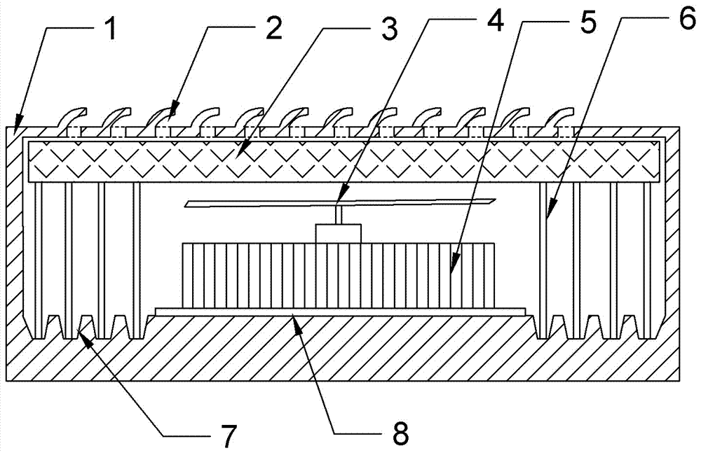
The invention relates to the technical field of switching power supplies, specifically a dew-removing cooling switching power supply. The power supply comprises a housing, and the interior of the housing is provided with an integrated circuit board. The integrated circuit board is provided with a main circuit, a control circuit, a detection circuit, a protection circuit and an auxiliary power supply. The interior of the housing is also provided with a cooling fan for cooling, and the housing is provided with a heat dissipation hole for ventilation, a power input jack and a power switch for controlling the power input. The interior of the housing is also provided with sponge which is installed at the heat dissipation hole. The inner wall of the bottom of the housing is provided with a dew collection groove for collecting dew. The interior of the housing is fixedly provided with a fine pipe, wherein one end of the fine pipe is inserted into the dew collection groove, and the other end of the fine pipe is inserted into the sponge. The power supply provided by the invention can solve a problem that a conventional switching power supply cannot remove dew effectively, and can achieve the functions of dust collection and cooling at the same time.
Description
technical field [0001] The invention relates to the technical field of switching power supplies, in particular to a dew-removing and cooling switching power supply. Background technique [0002] Switching power supply is a kind of power supply that uses modern power electronic technology to control the time ratio of switching on and off to maintain a stable output voltage. Switching power supply products are widely used in industrial automation control, military equipment, scientific research equipment, LED lighting, industrial control equipment, communication equipment, power equipment, instrumentation, medical equipment, semiconductor refrigeration and heating and other fields. The working environment of switching power supply is generally harsh. In order to ensure that the switching power supply can work normally in thunderstorm weather, smog weather, and high temperature weather, the switching power supply needs to have excellent rainproof, moisture-proof, lightning-proo...
Claims
Login to View More Application Information
Patent Timeline
 Patent Type & AuthorityApplications(China)
IPC IPC(8): H02M1/00H05K7/20
CPCH02M1/00H05K7/20909
Inventor钟俊
OwnerCHONGQING LUGE TECH CO LTD