Optical arrangement, lighting system and illumination method

a technology of optical arrangement and lighting system, applied in the direction of lighting and heating equipment, semiconductor devices for light sources, instruments, etc., can solve the problems of inability to independently control the level or intensity of light provided to each desk or workstation, and high installation cost of troffer-based lighting systems. , to achieve the effect of avoiding mains supply, facilitating installation, and simplifying the installation process

Active Publication Date: 2020-01-28
SIGNIFY HLDG BV
View PDF20 Cites 0 Cited by
  • Summary
  • Abstract
  • Description
  • Claims
  • Application Information

AI Technical Summary

Benefits of technology

[0018]The invention hence provides a reflector panel type solution for enabling re-direction for ground-based lighting to a specific tailored location within a space. Control over directionality is achieved through provision of a reflector array and lens array pair having an adjustable relative displacement. By controlling this relative displacement, an optical interaction between the two arrays is changed, thereby varying an angle of deviation between incoming light received at the optical arrangement and outgoing light departing from the optical arrangement. In this way, control over the directionality of illumination can be achieved.
[0048]The lighting system enables illumination to be controllably provided to a desired region within a space by controllably adjusting the relative positioning of the lens array and reflector array. Since the output directionality of the optical arrangement can be controllably adjusted, illumination can be provided to a desired location in the space (i.e. a specific worker's / user's desk) while positioning the luminaire at a far wider range of suitably convenient locations.

Problems solved by technology

One disadvantage of troffer-based lighting solutions is that light is typically distributed uniformly across an illuminated space, leading to much wasted light, where light is directed to areas or regions within the space (for example in between desks or workstations in an office) where illumination is not required (at least at the same intensity).
Additionally, in the case of illumination within an office for instance, the level or intensity of the light provided to each desk or workstation cannot be independently controlled, since light is distributed in a uniform, non-discriminatory way across all regions within the illuminated space.
Currently known troffer-based lighting systems are also typically expensive to install (due to the requirement to run electronic cabling to across the ceiling to each troffer) and require relatively high levels of maintenance (fixing broken lamps / sensors, changing commissioning settings, fixing commissioning errors).
As mentioned above, known troffer systems do not enable local tailoring of illumination characteristics, such as brightness, colour, directionality or for implementing individual timing or scheduling (such as to fit with individual circadian rhythms).
A white ceiling leads to light being spread in unwanted directions, and therefore wasted.
However, as alternative for ceiling-based lighting such as a troffer-based lighting system, the known reflector panels offer very limited degree of control over the directionality of the reflected light.
Often, this is not practical, due to constraints imposed by the layout of the office (or other space), and hence light is typically cast onto areas or regions which are not precisely congruous with workstation locations.
This limits possibilities for individualised control of provided lighting.

Method used


Image

  • Optical arrangement, lighting system and illumination method
  • Optical arrangement, lighting system and illumination method
  • Optical arrangement, lighting system and illumination method

Examples


Embodiment Construction

[0068]It should be understood that the Figures are merely schematic and are not drawn to scale. It should also be understood that the same reference numerals are used throughout the Figures to indicate the same or similar parts.

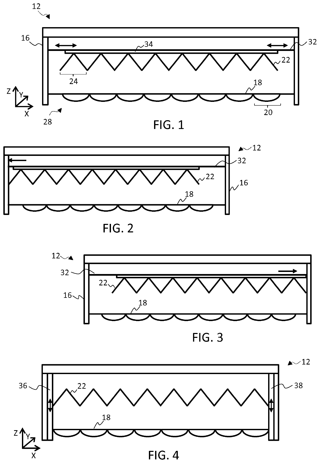
[0069]The invention provides an optical arrangement for illuminating a region within a space comprising a reflector array and lens array having an adjustable relative displacement. Each lens of the lens array is arranged to receive light from a first location within the space and to direct it onto one of the reflectors of the reflector array. Each lens is further configured to receive light reflected back from the reflector array and redirect it toward a second location within the space. By adjusting the relative displacement between the two arrays, the position of the second location can be configured.

[0070]FIG. 1 schematically illustrates a cross-sectional view through a first example optical arrangement 12 in accordance with one or more embodiments of the ...


PUM


Abstract

An optical arrangement for illuminating a region within a space comprises a reflector array and lens array having adjustable relative displacement. Each lens of the lens array is arranged to receive light from a first location within the space and to direct it onto one of the reflectors of the reflector array. Each lens is further configured to receive light reflected back from the reflector array and redirect it toward a second location within the space. By adjusting the relative displacement between the two arrays, the position of the second location can be configured.

Description

CROSS-REFERENCE TO PRIOR APPLICATIONS[0001]This application is the U.S. National Phase application under 35 U.S.C. § 371 of International Application No. PCT / EP2017 / 073663, filed on Sep. 19, 2017, which claims the benefit of European Patent Application No. 16190046.9, filed on Sep. 22, 2016. These applications are hereby incorporated by reference herein.FIELD OF THE INVENTION[0002]This invention relates to an optical arrangement and lighting system for illuminating a region within a space, and in particular, for illuminating a region by means of reflection of a remotely positioned illumination source.BACKGROUND OF THE INVENTION[0003]Office lighting is most commonly provided by means of ceiling ‘troffers’, which are (typically rectangular) light fixtures designed to accommodate fluorescent or LED light sources, and configured to fit into a modular dropped ceiling grid. Troffers typically comprise reflective and / or diffusive optical components to modulate direction or character of emi...

Claims


Application Information

Patent Timeline
Patent Type & Authority Patents(United States)
IPC IPC(8): F21V14/04F21V14/06F21V7/00F21V13/04F21Y115/10
CPCF21V13/04F21V7/0008F21V14/04F21V14/06F21Y2115/10F21V5/007F21V7/0083F21Y2105/10G02B26/08
Inventor HEEMSTRA, TEWE HIEPKE
Owner SIGNIFY HLDG BV
Why Eureka
Try Eureka