Vertically polarized antenna

A vertically polarized antenna and metallized through-hole technology, applied in the direction of circuits, waveguide openings, etc., can solve the problems affecting antenna directivity, electromagnetic wave diffraction, discontinuity, etc., to improve the directivity of the E surface and increase the size of the antenna Size, effect of suppressing backward radiation

Inactive Publication Date: 2015-12-02
UNIV OF ELECTRONIC SCI & TECH OF CHINA
View PDF2 Cites 5 Cited by
  • Summary
  • Abstract
  • Description
  • Claims
  • Application Information

AI Technical Summary

Problems solved by technology

[0005] Since the height of the substrate-integrated waveguide (the plane where the electric field E is located, that is, the plane perpendicular to the substrate, referred to as the E plane) is the thickness of the dielectric substrate, it is often only a few millimeters high, which is far smaller than the size of ordinary waveguides. Larger discontinuities cause impedance mismatch at the same time, and a large number of electromagnetic waves are reflected back to the inside of the substra

Method used


Image

  • Vertically polarized antenna
  • Vertically polarized antenna
  • Vertically polarized antenna

Examples


Example Embodiment

[0030] The following describes the implementation of the present invention through specific specific examples, and those skilled in the art can easily understand other advantages and effects of the present invention from the content disclosed in this specification. The present invention can also be implemented or applied through other different specific embodiments, and various details in this specification can also be modified or changed based on different viewpoints and applications without departing from the spirit of the present invention.

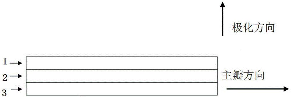
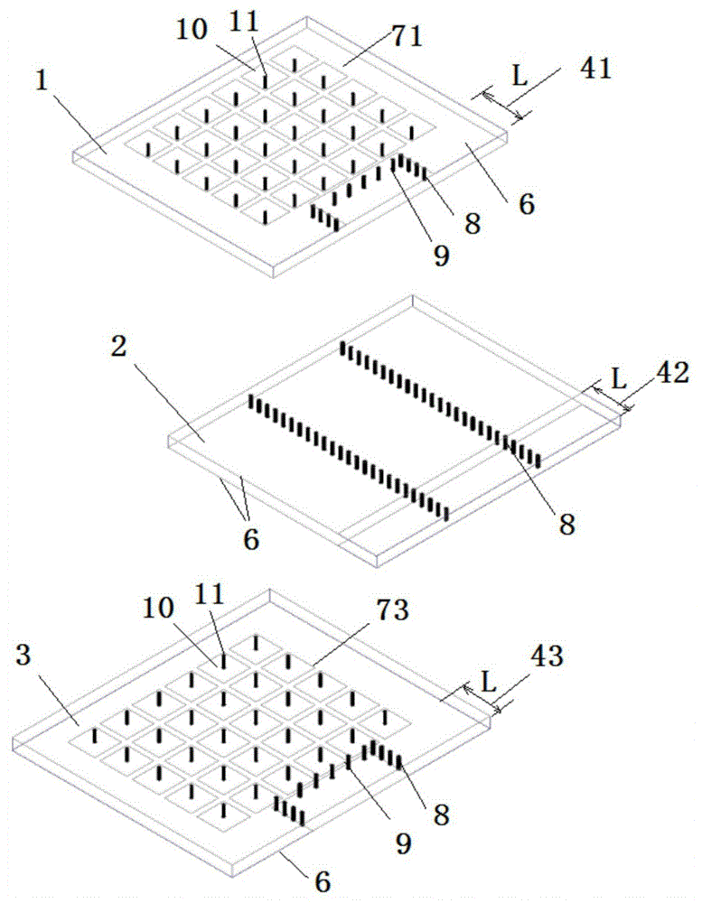
[0031] A vertically polarized antenna, including 3 layers of dielectric plates, from top to bottom, the first layer 1, the second layer 2, and the third layer 3. The right end of each layer has a section extending from the right edge of the dielectric plate to the left The L areas of the L area are 71, 72, 73 respectively. The entire second layer 2, the first layer L area 41, and the third layer L area 43 together form a stepped substrate ...


PUM


Abstract

The present invention provides a vertically polarized antenna which comprises three layers of the dielectric plates which are a first layer, a second layer and a third layer. The right end of each layer of dielectric plate has a section of L area extending leftward from the right boundary of the dielectric plate, a stepped substrate integrated waveguide structure whose L area height is higher than that of the left side of the L area is formed by the whole second layer, a first layer L area and a third layer L area together. The length of the L area is L. The vertically polarized antenna comprises the stepped substrate integrated waveguide structure, through using the step transition technology is employed at an E plane, for E plane discontinuities, the transition of the E plane is carried out directly, the antenna standing wave is greatly improved, the efficiency is high, the size is only changed for several millimeters, according to the E plane transition structure, the antenna E plane directivity can be improved, at the same time through laying electromagnetic band gap structures at upper and lower surfaces, in the condition of not enlarging the antenna size, the backward radiation is greatly inhibited, and the antenna E plane directivity is further improved.

Description

technical field [0001] The invention belongs to the field of antennas, in particular to a vertically polarized antenna whose polarization direction is perpendicular to a circuit board. Background technique [0002] For indoor communication, compared with the traditional base station antenna, the ceiling-mounted small base station antenna has the advantages of small size, does not occupy indoor floor space, is far away from ground shelters, increases the distance between the base station and the user group, and reduces potential radiation hazards. It is the future development direction of indoor small base stations. [0003] Base station antennas generally use horizontal / vertical dual-polarized antennas. For the generation of vertically polarized components, the traditional method is to weld a section of vertical cylindrical or conical metal on a horizontally placed circuit board, which is equivalent to a monopole antenna. Electromagnetic waves, because this method requires ...

Claims


Application Information

Patent Timeline
IPC IPC(8): H01Q13/06
Inventor 陈波唐清悟黄皖菁蒋元俊景心平崔满堂
Owner UNIV OF ELECTRONIC SCI & TECH OF CHINA
Why Eureka
Try Eureka