Geogrid or mesh structure

Active Publication Date: 2006-02-21
TENSAR TECH
View PDF25 Cites 29 Cited by
  • Summary
  • Abstract
  • Description
  • Claims
  • Application Information

AI Technical Summary

Benefits of technology

[0010]Geogrids of the invention provide pairs of angled strands between the transverse bars or further oriented strands and reduces any tendency for relative movement between the strands and the soil, creating a stiffer and more effective reinforcement anchor. In effect, it has been found that by careful choice of the number and geometry of the holes in the starting material, angled strands could be produced as an integral feature of the geogrid design. Possible advantages of such geogrids can be increased in-plane torsional stiffness or rigidity (important for interlock), increased flexural modulus, improved multi-directional property performance, diverse soil or aggregate interlock properties, greater resistance to shear forces and the enhanced ability to carry and/or distribute greater loads in general and radial loads in particular. If a piece of the geogrid is tested with a fully restrained periphery, for a given load normal to the plane of the geogrid, the deflection is lower than for comparable conventional biax geogrids (increased flexural modulus), and the deflection is less localised around the point of application of the load, i.e., is more evenly distributed across the sample. This indicates that the load on the conventional geogrid is born by a relatively small number of strands within the immediate loading area (a four-strand junction) whereas the geogrid of the invention has more paths to carry the load away from the loading area (an at least six-strand junction). Testing was carried out only with a relatively small load, but it is believed that there is good correlation between the applied load and the corresponding deflection of the geogrid and that extrapolations to higher loads would be valid. Compared to a comparable conventional biax geogrid, the geogrid of the invention has a combination of tensile strength and stiffness properties that improves the provision of multi-axial performance by permitting the dispersion of an applied load over 360°. All these properties are important when considering the interlock of the geogrid with soil or aggregate.
[0011]In one geogrid, triangular meshes of the geogrid provide a robus

Problems solved by technology

However, it has been appreciated that there are weaknesses

Method used


Image

  • Geogrid or mesh structure
  • Geogrid or mesh structure
  • Geogrid or mesh structure

Examples


Example

[0059]FIG. 17 is a graph of deflection against force for the geogrid of Example 2 (circular plots) and for a comparable conventional biax geogrid (square plots) when a load is applied to a centre junction of a sample which is clamped all around its periphery.

Example

FIGS. 1 TO 6—FIRST EMBODIMENT

[0060]In one procedure, the starting material 1 shown in FIG. 1 was a strictly uniplanar sheet of extruded plastics material having planar parallel faces. Holes 2 were punched in an array of hexagons 3 of substantially identical shape and size so that substantially each hole 2 was at a corner of each of three hexagons 3. For experimental purposes, truth lines 4 are shown printed on the central area of the portion of starting material 1 represented.

[0061]The starting material 1 was heated and a first stretch was applied in the notional MD, i.e. in a direction substantially parallel to the MD sides of the hexagons 3 indicated in FIG. 1, using parallel clamps which engage the edge zones of the starting material 1 and are then drawn apart linearly. Although simple clamps were used, the term MD and TD are used for convenience. Due to the strength configuration of the starting material 1, the first stretch stretched out strand-forming zones 5 between adjacent ...

Example

FIG. 7 and Example 1

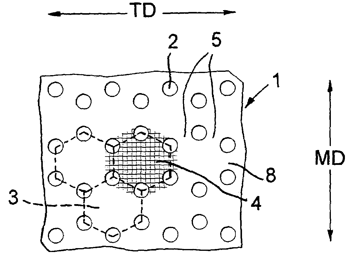
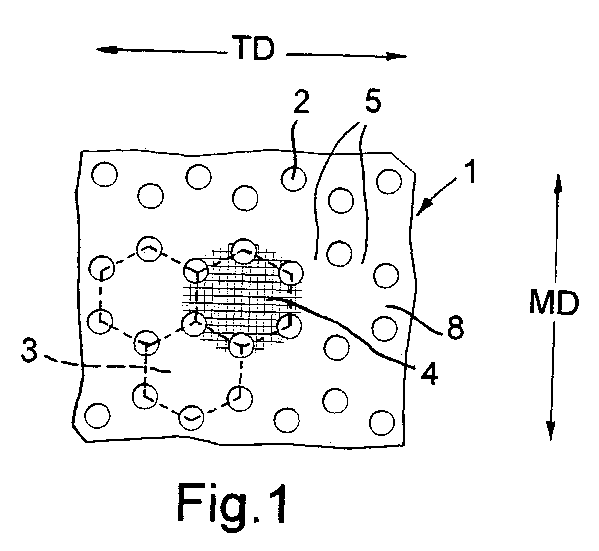
[0069]FIG. 7 is an enlarged view of part of the starting material 1 of FIG. 1 and indicates the pitches (the distances between the centres) of the holes 2. The starting sheet 1 was nominally 4.7 mm thick polypropylene with 2% carbon black additive and the punch size for the holes 2 was 5 mm diameter. It will be seen that the hexagons 3 do not have equal-length sides but are slightly foreshortened in the MD and in each hexagon 3, the ratio of the distance between the centres of the two opposite holes 2 on the MD axis of the hexagon 3 (18.5 mm) to the distance between the other remaining pairs of opposite holes 2 (21.7 mm) is 0.85:1 (or 1:1.17). The major MD pitch:minor MD patch ratio is 2.625:1. The ratio of the distance apart of the centres of adjacent holes to the diameter of the holes is 2.1:1 and 2.06:1, respectively.

[0070]The starting material 1 was given a first (notional MD) stretch to an overall stretch ratio of 3.86:1, and was allowed to relax to give a s...


PUM

PropertyMeasurementUnit
Thicknessaaaaaaaaaa
Thicknessaaaaaaaaaa
Pressureaaaaaaaaaa

Abstract

To make an oriented plastics material geogrid 10 in which oriented strands 6, 9 form triangular meshes with a junction 11 at each corner and six of the strands 6, 9 meet at each junction 11, a plastics material sheet starting material 1 has holes 2 in an array of hexagons 3, opposite holes 2 of each hexagon being aligned in the machine direction, and the starting material 1 is stretched first in the machine direction and secondly in the transverse direction. In the eventual geogrid 10, the centre portions of the hexagons in the starting material 1 form the junctions 11. The centres of the junctions 11 are slightly biaxially oriented, but at the edges of the junctions 11, the orientation of the edge of substantially each strand 6 or 9 runs around the edge of the respective junction 11 and into the edge of the next strand 6 or 9. During the second stretch, restraint can be applied in the first stretch direction and discontinued before the material is allowed to relax in the second stretch direction. If desired, the procedure can be terminated after the first stretch, to produce a uniaxially-oriented geogrid. By using a starting material 21 which has through holes 22 and weakened zones 23, it is possible to form the geogrid of the invention from a starting material 21 having a rectangular array of through holes 22.

Description

BACKGROUND OF THE INVENTION[0001]The present invention relates in general to geogrids though there is some applicability to mesh structures in general. A geogrid is a grid whose primary purpose is to strengthen or reinforce soil and has open meshes into which soil particles can lock. If made by orienting a plastics starting material, the starting material would normally have a thickness greater than about 1, 1.5 or 2 mm. A geogrid is in effect made up of strands (also called ribs) which are interconnected at bars running across the geogrid in the TD or are interconnected at junctions (also called nodes or intersections), whether or not the strands are continuous throughout the geogrid as they would be in the case of say a woven geogrid. The thickness of a geogrid, as measured at the junction, would be greater than about 0.5 mm or 0.75 mm and may well be greater than about 1.00 mm or 1.5 mm or 2.0 mm. The mesh size (also called mesh opening size or aperture size) should if possible b...

Claims


Application Information

Patent Timeline
IPC IPC(8): B29D7/00E02D17/20B29C55/00E02D17/18B29C55/14B29D28/00E02D29/02
CPCB29C55/14E02D29/0241B29D28/00Y10T428/24273B29C55/02B29C55/10
Inventor WALSH, ANTHONY T.
Owner TENSAR TECH
Why Eureka
Try Eureka