Ionisation vacuum gauge

Inactive Publication Date: 2005-02-10
AGILENT TECH INC
View PDF8 Cites 31 Cited by
  • Summary
  • Abstract
  • Description
  • Claims
  • Application Information

AI Technical Summary

Benefits of technology

Advantageously, the vacuum gauge performance can be enhanced by acting on the characteristics of the electron motion, by introducing magnetic and/or electric fields.
Introducing a magnetic

Problems solved by technology

The major drawback of that kind of vacuum gauges is related to the nature of the electron-emitting cathode.
Moreover, the phenomenon of electron emission by thermionic effect entails high power consumption, long response times and a non-negligible pollution of the surrounding environment due to the release of impurities.
More particularly, the vacuum gauge

Method used


Image

  • Ionisation vacuum gauge
  • Ionisation vacuum gauge
  • Ionisation vacuum gauge

Examples


first embodiment

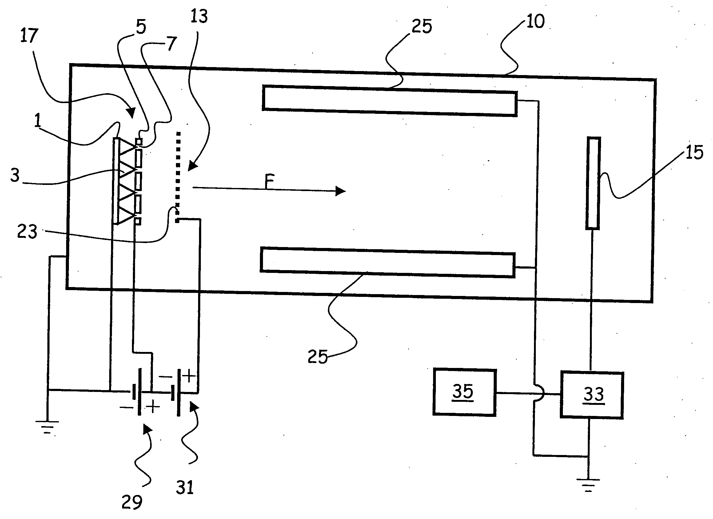
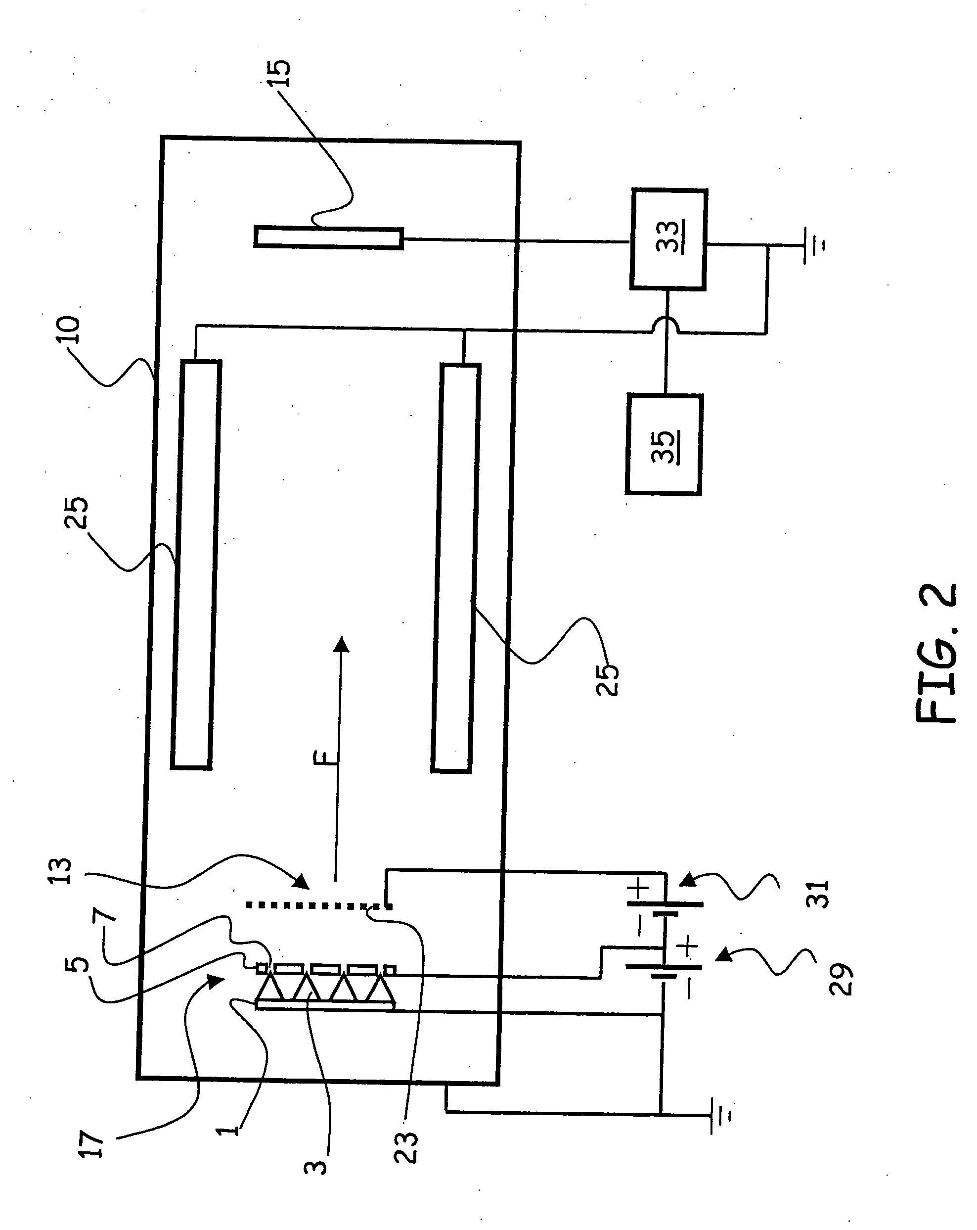
Referring to FIG. 2, there is shown the vacuum gauge according to the invention. A chamber 10 encloses the volume containing a gaseous material, the residual pressure of which is to be measured. The vacuum gauge comprises a cathode 17 capable of emitting electrons, a grid-shaped anode 13, capable of accelerating the electrons emitted by cathode 17, and a plate or collecting electrode 15, which is intended to collect the gas ions produced by electron collisions with the atoms or molecules of said gaseous material.

Anode 13 is made as a substantially plane grid and is placed opposite cathode 17, at short distance therefrom. Thus, the electrons emitted by cathode 17 are accelerated into a beam oriented according to a preferential initial direction (denoted by arrow F), substantially perpendicular to the plane of anode 13. Plate 15 is made as a plane plate, in register with and substantially parallel to grid-shaped anode 13.

According to the first embodiment as shown in FIG. 2, cathode...

second embodiment

Turning to FIG. 3, there is shown a second embodiment which differs from the previous one in the shape of the grid-shaped anode, here denoted by reference numeral 113.

Anode 113 is a substantially parallelepiped cage, having a face 113a parallel to cathode 17 and placed at a short distance therefrom. Thus, the electrons emitted by cathode 17 are accelerated through face 113a of anode 113 according to a preferential initial direction (denoted by arrow F), substantially perpendicular to the plane of face 113a.

Collecting plate 15 is placed opposite face 113a, in correspondence of open base 114 of grid 113.

Note that using a parallelepiped grid 113 allows for increasing the vacuum gauge sensitivity. Actually, being both plate 15 and the walls of chamber 10 grounded, the ions could be attracted by the walls rather than by plate 15, thereby creating an ion dispersion effect. Using a parallelepiped grid 113, which is closed except for opening 114 in correspondence of plate 15, allows fo...

third embodiment

Turning now to FIG. 4, there is shown the vacuum gauge according to the invention, which differs from the previous ones in the arrangement of collecting plate 15.

In the previously disclosed embodiments, plate 15 is placed opposite the cathode and lies in a plane substantially parallel to the cathode itself and perpendicular to preferential direction F of the electron beam.

In the embodiment shown in FIG. 4, plate 15 lies in a plane substantially perpendicular to the plane of cathode 17, and hence it is located in a plane parallel to preferential initial direction F of the electron beam. Thus, the ions and the ionised molecules attracted towards plate 15 move towards the plate in a direction substantially perpendicular to that of the electron beam.

Thus, interactions between the electron source (cathode 17) and collecting plate 15 are limited. More particularly, the photoelectric effect on plate 15 due to X rays emitted by grid 113′ is significantly limited, whereby the sensitivit...


PUM


Abstract

The present invention relates to an ionisation vacuum gauge for measuring the residual pressure of a gaseous material remaining in a container (10), more particularly after operation of a vacuum pump. The gauge comprises an electron-emitting cathode (17), a grid (13) for accelerating the electrons emitted by the cathode and a plate (15) collecting the ions and/or the ionised positive molecules of the gas, wherein said plate is placed outside said grid. Measuring the plate current by a galvanometer allows determining the value of the residual pressure inside the container.

Description

FIELD OF THE INVENTION The present invention relates to an ionisation vacuum gauge. More particularly, the present invention relates to an ionisation vacuum gauge for measuring the residual pressure of a gaseous material remaining in a container, for instance, after operation of a vacuum pump, the gauge being of the kind comprising an electron-emitting cathode, a grid for accelerating the electrons emitted by the cathode and a plate collecting the ions or the ionised positive molecules of the gas, wherein the measurement of the plate current by a galvanometer allows determining the value of the residual pressure inside the container. BACKGROUND OF THE INVENTION Two kinds of vacuum gauges are known: thermionic emission vacuum gauges (also called hot cathode vacuum gauges), and field emission (or cold cathode) vacuum gauges. In thermionic emission vacuum gauges, the electron source consists in one or more filaments, for instance of tungsten, brought to incandescence. A typical exa...

Claims


Application Information

Patent Timeline
IPC IPC(8): G01L21/34H01J41/06
CPCG01L21/34
Inventor CORREALE, RAFFAELE
Owner AGILENT TECH INC
Why Eureka
Try Eureka